Advertisement
Advertisement

Related Manuals for Tie Down Engineering 660E

Summary of Contents for Tie Down Engineering 660E
- Page 1 Model 660E Brake Actuator Owner’s Manual...
-
Page 2: Table Of Contents
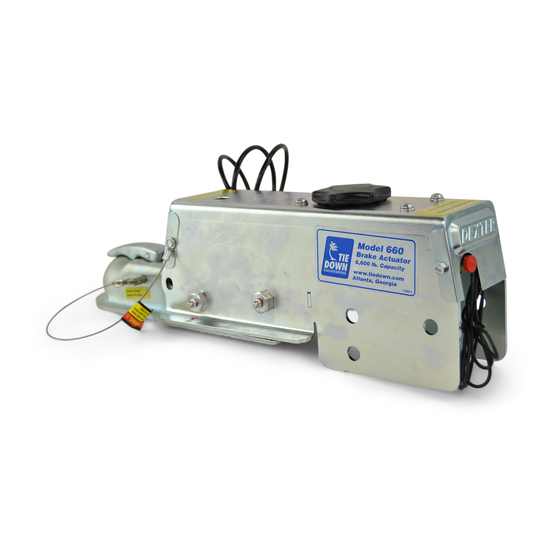
Installation Instructions and Service Manual Model 660E Actuator for Trailer Brakes 6,600 lbs. Capacity Drum or Disc Brakes Table of Contents Page Actuator Installation Instructions Hitching the Trailer Vehicle Wiring - Free Backing Brake Solenoid Actuator Maintenance Warnings Bleeding Instructions... - Page 3 IMPORTANT: READ AND UNDERSTAND THE ENTIRE INSTRUCTION/ASSEMBLY PROCEDURE BEFORE INSTALLING YOUR BRAKES AND ACTUATOR. The Model 660E works by the “surge” or “push” of the trailer toward the tow vehicle. This automatically synchronizes the trailer brakes with the tow vehicle axle brakes. When the trailer pushes against the tow vehicle, the actuator telescopes together and applies the force to the master cylinder, supplying hydraulic pressure to the brakes.
-
Page 4: Hitching The Trailer
1. The vehicle, towing hitch and ball must have a rating equal to or greater than the trailer G.V.W.R. 2. Model 660E will accept 2” or 50mm trailer hitch balls only. Trailer balls larger than 2.00” (50mm) or out of round will not fit the coupler or may result in coupler failure. - Page 5 DANGER: Tongue weight beyond rating limits will interfere with performance of actuator, and braking system, and the tow vehicle. 9. The actuator is designed for use with Free-Backing trailer brakes. To block braking action, (in order to back up) with other types of brakes, use an electric solenoid.
-
Page 6: Warnings
Braking and Trailering Warnings WARNING Actuator and brakes should always be flushed with fresh water after using trailer in corrosive conditions. This includes salt water, fertilizers and other corrosive materials. Before storing trailer remove brakes and clean thoroughly. It is also recommended to repack the bearings at the same time. - Page 7 WARNING A minimum of 5% tongue weight and a maximum 10% tongue weight of the trailer G.V.W.R. must be located on the hitch ball. The Trailer tongue should be parallel to the ground. To much weight can cause premature brake actuation and loss of control of the towing vehicle.
-
Page 8: Bleeding Instructions
Bleeding Instructions To bleed master cylinder and brakes, install bleeder hose on first wheel cylinder to be bled; if tandem axle trailer, bleed furthermost axle first, and the furthermost brake on that axle first. Use a loose end of hose from the bleeder valve submerged in a glass container of brake fluid to observe bubbling (hose must be submerged into clean brake fluid to keep air from traveling back into the brake cylinder). - Page 9 FRONT FRONT Push the screwdriver forward and back to pump the master cylinder. (See 2B). The bleeding operation for that brake is complete when bubbling stops. Be sure to tighten bleeder screw securely. Each wheel cylinder must be bleed until all air is out of the lines.
- Page 10 Model 660E/660 Replacement Parts 1 & 6 Page 9...
- Page 11 Model 660E/660 Replacement Parts Model 660E Model 660 “Enclosed” “Open” Master Cylinder Master Cylinder Item # Part # Description 70461K Disc Brake Master Cylinder Kit “Open Model” with gasket, Includes: master cylinder and cap, 4 mounting screws with washers, 2 rollers with matching nuts and bolts 70461KD Drum Brake Master Cylinder Kit “Open Model”...
- Page 12 Model 66 Replacement Parts 1 & 6 Page 11...
- Page 13 Model 66 Replacement Parts Model 66 Master Cylinder Item # Part # Description 47260K Disc Brake Master Cylinder Kit “Lever Latch” with gasket and fluid baffle, includes: master cylinder and cap, 4 mounting screws with washers, 2 rollers with matching nuts and bolts 47268K Drum Brake Master Cylinder Kit “Lever Latch”...
-
Page 14: Limited Warranty
TIE DOWN ENGINEERING LIMITED WARRANTY Limited Warranty TIE DOWN ENGINEERING (“TIE DOWN”) warrants its products to be free from defects in material and workmanship for one year from date of delivery to the original purchaser when properly installed, used and maintained by the purchaser. - Page 15 To Obtain Technical Assistance: To enable TIE DOWN to respond to a request for assistance or evaluation of customer or user operating difficulty, please provide at a minimum the following information by calling 1-800-241-1806: • Model number, serial number and all other data on the specific component which appears to be involved in the difficulty.
-
Page 16: Tie Down Engineering
Model 660E Brake Actuator Owner’s Manual TIE DOWN ENGINEERING 255 Villanova Drive SW, Atlanta, GA 30336 (404) 344-0000 • Fax (404) 349-0401 ISO 9001:2008 Certified Company © 2014 TIE DOWN, Inc. ALL RIGHTS RESERVED Instruction #08218...
Need help?
Do you have a question about the 660E and is the answer not in the manual?
Questions and answers
Instructions on how to replace emergency brake away cable on Tie Down 660
To replace the emergency breakaway cable on a Tie Down Engineering 660E actuator:
1. Identify the correct cable: Use part #50305 if your actuator has a serial number 16021 or above. This is the emergency stop (breakaway) cable with a button stop.
2. Remove the old cable: Locate the existing breakaway cable on the actuator (reference #3 in the schematic). Disconnect it from the actuator and its mounting point.
3. Install the new cable: Attach the new cable (part #50305) in the same position as the old one, ensuring the button stop is properly seated and secured.
4. Verify function: Ensure the cable moves freely and activates the emergency braking system when pulled.
Always verify the serial number of your actuator before ordering and installing parts.
This answer is automatically generated
How may I order the 3/8 to 5/16 inch brass fitting, which connects my brake line to the outlet of the master cylinder? It is at the rear, and is 90 degrees from the lock out solenoid. Where the red plastic cap is in the attached pic. Model TDE 660 on a 2015 venture aluminum twin axle vin 47GAA2327GB00016_ ?