AirCycler g2-k Training Manual
Hide thumbs
Also See for g2-k:
- Installation & user manual (11 pages) ,
- Installation testing manual (2 pages) ,
- Installation testing manual (2 pages)

Related Manuals for AirCycler g2-k


Summary of Contents for AirCycler g2-k
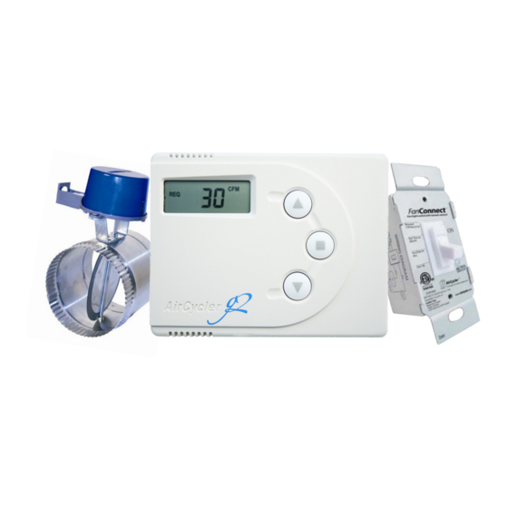
- Page 1 SIMPLE VENTILATION SOLUTIONS AirCycler® g2-k Training Guide VENTILATION MADE BREEZY!™ a breeze to install • a breeze to use...
-
Page 2: Table Of Contents
FanConnect™ Switch Wiring (Optional) 1.0 Theory of Operation 1.1 Operation Details 1.2 Operation Examples 2.0 AirCycler® g2 Operation 2.1 Reading the AirCycler® g2 2.2 Normal Operation Display 2.3 Entering Setup Mode 3.0 Setup Options 4.0 Calculated Flow Set Up 4.1 Setting Measured Supply Air Flow 4.2 Setting Measured Exhaust Air Flow... -
Page 3: Aircycler® G2-K Introduction
How does it work? The AirCycler® g2-k System is integrated with the home’s HVAC system. When the home’s furnace fan is turned on by the thermostat to provide heating or cooling, the AirCycler® g2 controller opens the motorized damper to let in a measured amount of fresh air. -
Page 4: Safety Considerations
The wires (R, C, & W ) from the air handler to the thermostat can run parallel with the wiring from the AirCycler® g2 to the air handler. The fan wire (G) must be interrupted by the AirCycler® g2. Some thermostats do not require a common (C) connection. - Page 5 RECORD ALL SETTINGS ON THE INSTALL STICKER PROVIDED. LIMITED WARRANTY WILL BE VOID IF THE STICKER IS NOT PRESENT. AC DOC 8.5 REV 7/2020...
-
Page 6: Aircycler® G2-K Wiring
AIRCYCLER® G2-K WIRING Class 2 conductors R - 24VAC Power C - Common W - Heating Gt - Fan From Thermostat Gf - Fan To Furnace V - Vent Ex - Exhaust Fan Vnc - Normal Closed Vent (To power spring-return... -
Page 7: Fanconnect™ Switch Wiring (Optional)
Anytime the light switch is turned on, Blue (light) the fan circuit is energized supplying power to the fan. Red (fan) The AirCycler® g2 controller can: 24VAC @100mA Any light • Read when the bath fan is on and Any fan... -
Page 8: Theory Of Operation
1.1 OPERATION DETAILS The AirCycler® g2 Furnace Fan Timer is integrated with the home’s central furnace fan so that any time the central fan is turned on by the thermostat to provide heating or cooling, the AirCycler® g2 opens the motorized damper to let in a measured amount of fresh air. - Page 9 After regular heating/cooling cycles, ventilation requirements for the hour were not met. At the end of the hour the AirCycler® g2 forced on the bathroom exhaust fan, via the FanConnect™ switch, to reach required ventilation. NORMAL CENTRAL FAN OPERATION + OCCUPANT EXHAUST USE...
- Page 10 After regular heating/cooling cycles and manual occupant use of bathroom exhaust fan (including 5 minute delay), there was not enough ventilation to meet requirements for the hour. At the end of the hour the AirCycler® g2 forced on the bathroom exhaust fan, via the FanConnect™...
-
Page 11: Aircycler® G2 Operation
If the central fan is running from a thermostat call, the THE THERMOSTAT FAN icon will show. HAS TURNED ON THE CENTRAL FAN If the AirCycler® g2 has forced on the central fan, the FAN and ON icons will show. PERCENTAGE OF THE AIRCYCLER® G2 VENTILATION COMPLETE HAS FORCED THE FAN If the exhaust (bath) fan is on, the EXH icon will show. -
Page 12: Setup Options
Enter measured hour, you can enter the total minutes per exhaust flow hour into the AirCycler® g2 during set *If using FanConnect™ switch Enter min/hour of exhaust Enter required continuous ventilation desired airflow required by code... -
Page 13: Setting Measured Supply Air Flow
Press MODE to save all settings and return to normal operation. CALCULATED FLOW SETUP IS COMPLETE The AirCycler® g2 will now return to normal operation OR continue pressing MODE for Optional Mixing Time, Operation Hours, and Exhaust Fan Delay Time Settings. See Sections 5.3-5.6 for details. -
Page 14: Calculated Time Setup
If you are not setting an ON and OFF time, press MODE and continue to section 5.6. If you select YES, the AirCycler® g2 will prompt you to enter the hour you would like the ventilation to begin and the hour you want it to end followed by the current time. -
Page 15: Current Settings
This shows the exhaust delay time set. 6.1 CURRENT SETTINGS To view the current settings that are programmed in the AirCycler® g2, press the DOWN arrow during Normal Operation. Press the DOWN arrow to advance to each setting. The display will show the following:... - Page 16 6.3 DISABLING THE AIRCYCLER® G2 Warning: It is not recommended to turn off the AirCycler® if the unit is used as a ventilation controller. 3.4.1 Remove the top of the controller from the base to stop power to the unit and remove any button battery in the unit.
- Page 17 RECORD ALL SETTINGS ON THE INSTALL STICKER PROVIDED. LIMITED WARRANTY WILL BE VOID IF THE STICKER IS NOT PRESENT. AC DOC 8.5 REV 7/2020...
-
Page 18: Installation Testing Guide
7.0 INSTALLATION TESTING GUIDE Testing the AirCycler® g2-k completed installation is an easy two step process: STEP 1 Test the FanConnect connection & operation (if using FanConnect™ switch) (tm) STEP 2 Test thermostat, damper and furnace connection and operation LCD DISPLAY... - Page 19 3. To set the AirCycler® g2 to “Inverse Slave Mode” - run the exhaust fan whenever the central fan is not running - enter Calculated Flow setup. Set Measured Supply Air Flow, Measured Exhaust Air Flow, and Required Constant Airflow to the same levels.
- Page 20 APPENDIX B ASHRAE 62.2 REFERENCE CHART Square Footage CFM Required: 7.5 CFM * (N+1) + A * 0.01 N = No. of Bedrooms A = Square Footage Technical Support: info@aircycler.com AC DOC 8.5 REV 7/2020...
Need help?
Do you have a question about the g2-k and is the answer not in the manual?
Questions and answers