Table of Contents
Advertisement
Quick Links
Advertisement
Table of Contents

Subscribe to Our Youtube Channel
Related Manuals for KAM OID

Summary of Contents for KAM OID
- Page 1 OPTICAL INTERFACE DETECTOR PTB 08 ATEX 1027 User Manual TEL +1 713 784 0000 FAX +1 713 784 0001 OIDMANUAL 1219 Email Sales@Kam.com KAM CONTROLS, INC. 3939 Ann Arbor Drive Houston, Texas 77063 USA www.KAM.com An ISO 9001 certified company...
-
Page 2: Table Of Contents
& temperature, and high-pressure steam refer to the Pipeline Operators’ “Health, Safety and Environmental Policy Procedures” to ensure safe installation. KAM CONTROLS, INC. reserves the right to make changes to this document without notice. KAM CONTROLS, INC. OIDMANUAL 1219... -
Page 3: Introduction
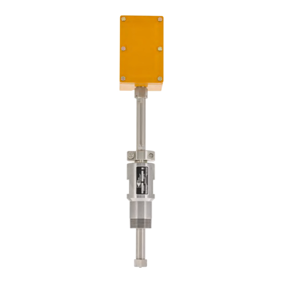
The simplicity of design and quality of engineering employed in the OID™ sensor mean there are no moving parts. The OID™ is comprised of an optical probe inserted into the fluid/flow and connected via fiber optic cable to the related transmit and receive electronics which are housed within an explosion-proof enclosure on the atmospheric end of the sensor. -
Page 4: Features
I N T R O D U C T I O N C O N T I N U E D FIG. 1-4 KAM OID™ AND API GRAVITY/DENSITOMETER ® APPLICATIONS FEATURES • Batching • Detects the interface of specialty fuels such as ULSD •... -
Page 5: Specifications
12" to 60" – Off-the-shelf lengths are 24", 30", 36", 48", and 60" (610 mm to 1524 mm) (Off-the-shelf 610 mm, 762 mm, 914.4 mm, 1219 mm, 1524 mm) Pipe size: 3/4" to 48" (20 mm to 1200 mm) Weight: from 10 lbs. (4.5 kg) KAM CONTROLS, INC. OIDMANUAL 1219... -
Page 6: Installation
KAM CONTROLS also strongly recommends that you utilize a preview (or out-station) OID™ sensor. This lets the operator decide how to optimize each batch cut prior to actually making the batch cut at the in-station and gives the operator more confidence in their decisions as well as the time to identify and resolve any issues that may arise during a critical interface. - Page 7 FLOW FLOW premature failure. FLOW FLOW DO NOT attempt to screw the OID™ sensor either in or out by hand. Always use a 1 1/4" or 1 3/8" wrench on the wrench flat below the electronics enclosure.
- Page 8 I N S TA L L AT I O N C O N T I N U E D INSTALLATION DO’S AND DON’TS DO NOT use teflon tape on the OID™ sensor threads. DO use liquid thread sealant. DO install the OID™...
-
Page 9: Main Line
I N S TA L L AT I O N C O N T I N U E D PRIOR TO INSTALLATION Remove all the protective packaging materials, and ensure that the OID™ sensor was not damaged during transit. MAIN LINE INSTALLATION The KAM OID™... - Page 10 This will prevent the OID™ shaft from sliding and the probe from getting damaged during mounting. Measure the distance (D1) from the outside diameter of main pipe to the end of the connection where the OID™ sensor is going to be installed. FIG. 3-5.
- Page 11 TID cannot be calculated until the Seal Housing is screwed into place. If you have not already done so, please screw your OID™ sensor into place now. You must then measure the Threaded Depth (TD) into the Valve or connection in order to calculate TID. You can do this by measuring the distance from the edge of the Valve or female connection to the top of the Seal Housing body and subtracting that distance from 5.25".
- Page 12 I N S TA L L AT I O N C O N T I N U E D If you have an OID™ with a Flanged Seal Housing, you may now attach it to the valve on the pipeline.
-
Page 13: Analyzer Loop
We recommend using thread sealant and not teflon tape for the OID™ sensor threads. CAUTION: DO NOT USE THE ENCLOSURE TO TIGHTEN OR LOOSEN THE OID. THIS CAN CAUSE THE PROBE TO COME UNDONE AND THE FIBER CABLE TO BREAK. Please refer to “Do’s and Don’ts” on pages 6-7 . -
Page 14: Wiring
• Non-used openings shall be sealed according to EN 60079-1, section 13.8. • The connecting lead of the OID shall be installed as permanent installation and as such that it is sufficiently protected against damage. TYPICAL POWER AND LOOP WIRING CONFIGURATION FIG. - Page 15 (2 Watts) POWER SUPPLY 4-20mA (+) 4-20mA (-) RECEIVER INPUT POWER (+) 24VDC POWER (-) (2 Watts) 4-20mA (+) 4-20 mA Loop Isolator 4-20mA (-) RECEIVER OUTPUT INPUT INPUT 4-20 mA Loop Isolator OUTPUT INPUT KAM CONTROLS, INC. OIDMANUAL 1219...
- Page 16 CAUTION: When electronics enclosure is open, be ex- RS485 (Modbus RTU) tremely careful to avoid any contact with interior fiber optic connections. Failure to do so could result in the OID malfunctioning. WIRING CONNECTION INSTRUCTIONS CONTINUE ON THE NEXT PAGE KAM CONTROLS, INC.
-
Page 17: Connecting The Oid
CONNECTING THE OID Proper Grounding of the OID™ sensor: Grounding the OID™ sensor through the 4-20 mA signal out and power lines is not adequate to protect the OID™ sensor against power surges. To ground the OID™ sensor, connect the chassis ground (if not already done) on the OID™ board (labeled CHS on the OID™... -
Page 18: Field Calibration
Only recalibrate the low end of the range in situations when all products are producing an output greater than 40%. Should the low end of the range require adjustment, please contact the KAM factory directly at +1 713 784 0000. FOR ALL OTHER TYPES OF ADJUSTMENTS CALL KAM CONTROLS, INC. +1 713 784 0000. - Page 19 F I E L D C A L I B R AT I O N C O N T I N U E D FIG. 4-1 Maximum Output Range Adjustment KAM CONTROLS, INC. OIDMANUAL 1219...
-
Page 20: Maintenance
M A I N T E N A N C E CLEANING AND INSPECTION Under normal operation, the KAM OID should not require cleaning, unless pipeline usage is limited to a small num- ber of products. Gasoline products or jet fuel in the pipeline will clean the OID without removal. - Page 21 Port = Select Port number assigned to your serial port or USB to serial converter g. Click on the Change button to save these settings. FIG. 5-2 Port tab Change to save Select port number Port settings KAM CONTROLS, INC. OIDMANUAL 1219...
- Page 22 To view output data, type the command "=ostart,c,20" and click on Send ASCII. See FIGs. 5-4 and 5-5 on pages 22 and 23. 11. Type the command "=ostop,c" to stop the data. Always do this before disconnecting. KAM CONTROLS, INC. OIDMANUAL 1219...
- Page 23 M A I N T E N A N C E C O N T I N U E D FIG. 5-4 (output data OID models serial numbers OID-15-1045 to OID-15-1061) Column 14 - CRC Cyclic Redundancy check for information only Column 13 –...
- Page 24 M A I N T E N A N C E C O N T I N U E D FIG. 5-5 (output data OID models serial numbers OID-15-1062 or higher)) Column 14 - CRC Cyclic Redundancy check for information only Column 13 –...
-
Page 25: Modbus Register
32bit Float 4-20mA Output Connect the Serial cable to the OID per Figure 3-15 on pg.15 Follow the instructions on pg. 19 “Diagnostics via RS232” Steps 1 to 9. Type the command “OIDmaster” and click on Send ASCII. FIG. A-1. You will get a confirmation that you have entered superuser mode. - Page 26 That number can be any number from 1 to 247 . FIG. A-2 To complete the change turn the OID power off, wait a couple of seconds and turn it back on. KAM CONTROLS, INC. OIDMANUAL 1219...
Need help?
Do you have a question about the OID and is the answer not in the manual?
Questions and answers