Table of Contents
Advertisement
USERS
A UA
GEBRUI ERSHA D EIDI G
BETRIEBSA
EITU G
A UE UTI ISATEURS
ALPHA ALTERNATOR
12/90, 12/130, 24/75, 24/110 & 24/150
HIGH OUTPUT ALTERNATORS WITH ALPHA PRO II REGULATOR
MASTERVOLT
Snijdersbergweg 93,
1105 AN Amsterdam
The ether a ds
Te
31 20 3422100
Fax
31 20 6971006
100000000002887/02
www
asterv t c
Advertisement
Table of Contents

Subscribe to Our Youtube Channel
Related Manuals for Mastervolt ALPHA ALTERNATOR 12/90


Summary of Contents for Mastervolt ALPHA ALTERNATOR 12/90
- Page 1 BETRIEBSA EITU G A UE UTI ISATEURS ALPHA ALTERNATOR 12/90, 12/130, 24/75, 24/110 & 24/150 HIGH OUTPUT ALTERNATORS WITH ALPHA PRO II REGULATOR MASTERVOLT Snijdersbergweg 93, 1105 AN Amsterdam The ether a ds 31 20 3422100 31 20 6971006 100000000002887/02...
-
Page 2: Table Of Contents
CONTENTS THIS MANUAL HAS TO BE READ IN COMBINATION WITH THE “APPENDIX ALPHA ALTERNATOR” CONTENTS: 100000000002887/02 GENERAL INFORMATION..........................4 Use of this manual ..........................4 Guarantee specifications ........................4 Quality ..............................4 Validity of this manual ......................... 4 Liability ..............................4 Changes to the Alpha alternator / Alpha Pro II regulator.............. - Page 3 CONTENTS COMMISSIONING ............................15 Selecting the charging mode ......................15 5.1.1 Commissioning when selecting MasterBus ..............15 Testing .............................. 15 5.2.1 Test prior to starting engine ....................15 5.2.2 In operation test ......................... 16 5.2.3 Voltage Settings ........................ 18 5.2.4 Absorption voltage adjustment ..................
-
Page 4: General Information
Mastervolt. GUARANTEE SPECIFICATIONS Mastervolt guarantees that this unit has been built according to the legally applicable standards and January 2013/ Alpha alternator - Alpha Pro II regulator / EN... -
Page 5: Safety Guidelines And Measures
Safety instructions and warnings are marked in this considered to be consistent with the intended manual by the following pictograms: purpose. Mastervolt is not liable for any damage resulting from the above. A procedure, circumstance, etc which deserves extra attention. -
Page 6: General Safety And Installation Precautions
Mastervolt non responsible from any claims arising electrical wiring regulations. out of the use of the Mastervolt parts in the life • Wrong use of the mode selector will lead to support equipment. serious damage to batteries, the Alpha alternator, the Alpha Pro II regulator and the cabling. -
Page 7: How It Works
Alpha Alternator together with the The Alpha Pro II voltage regulator controls the Alpha Pro II regulator from Mastervolt. This charging alternator’s output voltage. It is designed for optimal system is designed to provide a high output power at recharging of both wet, gel, AGM and li-ion batteries. -
Page 8: Temperature Compensated Charging
TECHNOLOGY Once the battery is fully charged, the Alpha Pro II regulator automatically switches over to the float phase. After Absorption phase (C) the Alpha Pro II regulator switches to Float voltage and stabilises this voltage to maintain the batteries in an optimum condition. Connected loads are powered directly by the charging system. -
Page 9: Installation
• The Alpha Pro II regulator alternator (including transmission V-belt) • A cable assembly for Mastervolt and Bosch approximately 50%. alternators • A Bosch adapter Example: • Battery temperature sensor At full output power, the required engine power to •... -
Page 10: Mounting Of The Alternator
(measured pair) transmission. As every engine differs from the other, Mastervolt can not give any specific mounting instructions for any particular engine. 4.4.2 Rotating direction The Alpha alternator is equipped with a bidirectional fan. Therefore it may rotate in either a clockwise or counter clockwise direction. -
Page 11: Electrical Connections
Before beginning batteries during charging, other charging equipment, with the connection of the wiring, make etcetera. Therefore Mastervolt strongly advises to the DC distribution voltage free. make an energy balance for the entire electrical installation. -
Page 12: Wiring Instructions
Alpha Pro II regulator. assembly must be connected to the [reg on] terminal of the Alpha Pro II regulator. Connect NOTE, only applicable for non-Mastervolt the other wire end through a switch (“S1”) with alternators: With most other brands there... -
Page 13: Connection Of A Tachometer (Optional)
INSTALLATION 4.5.4 Connection of a tachometer (optional) 4.5.5 Connection of an alternator indication If a tachometer is used, it should be connected lamp (optional) between the W terminal of the alternator (see To check the correct operation of the alternator often reference ) and the B–... -
Page 14: Use Of A Battery Isolator (Optional)
INSTALLATION 4.5.6 Use of a battery isolator (optional) When two or more battery banks need to be charged simultaneously, using a battery isolator is recommended. See figure 12 for installation details. See APPENDIX figures A-11, A-13 and A-14 for installation examples. CAUTION! If there is a battery isolator between the B+ terminal of the alternator and the positive (+) pole of the battery, both the red [+bat] wire and the brown [reg on] lines must be connected to the positive (+) pole... -
Page 15: Commissioning
COMMISSIONING 5 COMMISSIONING CAUTION! 3. Go to group ‘Battery’ and select the ‘Battery Check all wiring before commissioning: type’ present in your system positive connected positive (red cables), negative connected to negative (black cables) Commissioning of the Alpha alternator and the Alpha Pro II regulator involves two major parts: Figure Selecting... -
Page 16: In Operation Test
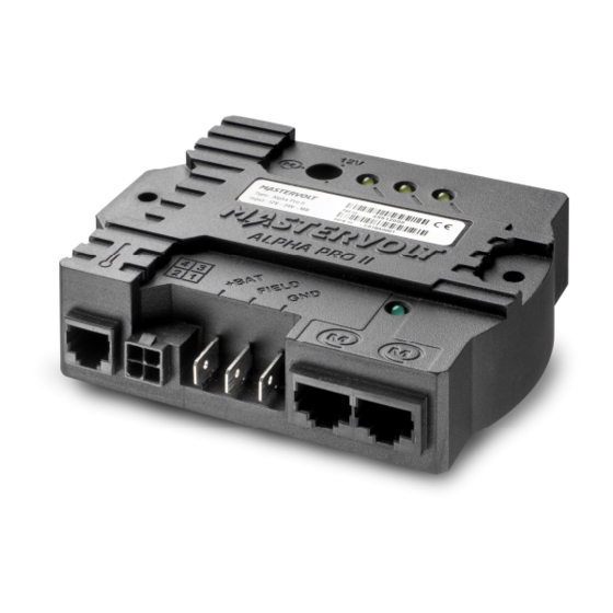
COMMISSIONING Energize the [reg on] terminal by either turning WARNING on the ignition switch (DO NOT START THE When the engine is running, be aware of ENGINE) or by putting a jumper across switch moving parts like V-belts. S1 (see figure 14). Check whether the 3 yellow LED’s start to blink. - Page 17 COMMISSIONING 8 9 10 Figure 15: Overview of the Alpha Pro II regulator 1. Settings selector 12/24V, MasterBus 2. Yellow LED to indicate Bulk phase 3. Yellow LED tot indicate Absorption phase 4. Yellow LED to indicate Float phase 5. Green LED to indicate MasterBus traffic 4.
-
Page 18: Voltage Settings
COMMISSIONING 5.2.3 Voltage Settings 5.2.7 Temperature compensation The Alpha Pro II regulator uses the [reg on] terminal battery temperature sensor included, (figure 16, connection 4) and the [gnd] terminal for compensates the charge voltage for deviating measurement of the battery voltage. battery temperatures. -
Page 19: Masterbus
Mastervolt also offers several interfaces like the Modbus interface, making even non-MasterBus devices suitable to operate in the MasterBus network. For central monitoring and control of the connected devices Mastervolt offers four different... -
Page 20: Masterbus Functions
MASTERBUS CAUTION! MASTERBUS FUNCTIONS Invalid settings of the Alpha Pro II can Adjustment of the settings of the Alpha Pro II can be cause serious damage to your batteries made via the MasterBus network (by means of a and/or the connected load! Adjustments remote control panel or a MasterBus - USB interface of settings may be undertaken by connected to a PC with MasterView System... -
Page 21: Configuration
MASTERBUS 6.3.4 Configuration Below parameters can be changed via the MasterBus network by means of a MasterView panel or by means of an interface connected to a PC with MasterView System software. Value Meaning Default Adjustable. range General Language Language displayed on a MasterBus English See specifications monitoring device... -
Page 22: Alpha Pro Ii Event Source List (Alpha Pro Ii As Event Source)
MASTERBUS Value Meaning Default Adjustable. range Shunt Shunt device Selection of the shunt to measure the battery voltage Alpha Pro II setup Factory settings Option to reset to factory settings Lock setup Option to lock the configuration settings. With the configuration locked, only the language and the device name can be changed. -
Page 23: Keep Alive Function
MASTERBUS 6.3.7 Keep alive function 6.3.11 Start Float SOC The Keep alive function is meant to keep the field Percentage of the maximum State of Charge to current at least at a value that is detectable by the enter Float stage. This setting can be used to save rpm meter. -
Page 24: Maintenance
MAINTENANCE 7 MAINTENANCE During maintenance of the Alpha Alternator, Alpha TENSION AND CONDITION OF V-BELTS. Pro II regulator and/or the engine, the Safety Loose belts will slip on the pulley, fail to turn the Guidelines & Measures are applicable at all times. alternator’s rotor and finally overheat the alternator. -
Page 25: Trouble Shooting
8 TROUBLE SHOOTING In case of any issue, we recommend consulting the Maintenance section first (see section 1). If you cannot solve a problem with the aid of the table below, contact your local Mastervolt Service Centre. See www.mastervolt.com. ISSUE... - Page 26 • Capacity of the charging system is increase charging capacity by using an too low. additional charger. Consult your Mastervolt representative for advice. Replace Alpha Pro II regulator. • Defective Alpha Pro II regulator. Alpha Pro II regulator does Nothing; this is a normal situation. If •...
-
Page 27: Technical Data
TECHNICAL DATA 9 TECHNICAL DATA SPECIFICATIONS ALPHA ALTERNATOR Model: 12/90 12/130 Part number: 48512090 48512130 Type enclosure (see APPENDIX): Charge current: 130A Recommended DC fuse 125A 160A Recommended DC wire size up to 3 m AWG2 - 35mm² AWG0 - 50mm² 3 m up to 5 m AWG0 - 50mm²... -
Page 28: Specifications Alpha Pro Ii Regulator
**See APPENDIX for outline drawings 29,5 [1.16] 95,0 [3.74] 109 [4.30] Figure 18: Dimension drawings of the Alpha Pro II regulator in mm [inch] Snijdersbergweg 93, 1105 AN Amsterdam, The Netherlands Tel : + 31-20-3422100 Fax : + 31-20-6971006 Email : info@mastervolt.com...
Need help?
Do you have a question about the ALPHA ALTERNATOR 12/90 and is the answer not in the manual?
Questions and answers
Absorption led comes on at ignition then goes out no leds at all yet getting charge 27.5 volts
If the absorption LED on a Mastervolt ALPHA ALTERNATOR 12/90 comes on at ignition and then goes out, but the system is still charging at 27.5 volts, it indicates that the charging system has transitioned from the bulk phase to the absorption phase. In this phase, the battery voltage has reached the absorption voltage, and the charging continues at a controlled rate until the battery is fully charged. The system is still operating normally, and the voltage of 27.5V suggests it is maintaining the absorption charge.
This answer is automatically generated
How do I test the alpha regulator
To test the Mastervolt Alpha Alternator 12/90 regulator, follow these steps:
1. Check Installation: Ensure all bolts are securely mounted and verify the alignment and tension of the V-belts.
2. Use a Digital Meter: A hand-held digital meter or a battery monitor (such as the MasterShunt) can be used to check voltage.
3. Monitor LED Indicators: When the absorption time has elapsed, the green float LED will illuminate, indicating the float mode has started.
4. Verify Settings: Depending on your configuration, the regulator may switch to float mode before reaching 100% state of charge (SOC).
5. Troubleshoot if Needed: If issues arise, refer to the troubleshooting section in the manual.
These steps ensure the regulator is functioning correctly and the charging system is ready for operation.
This answer is automatically generated