Advertisement
Quick Links
Advertisement

Related Manuals for FrSky RB-30

Summary of Contents for FrSky RB-30
- Page 1 RB-30/RB-40 Manual Version 1.0 FrSky Electronic Co., Ltd.
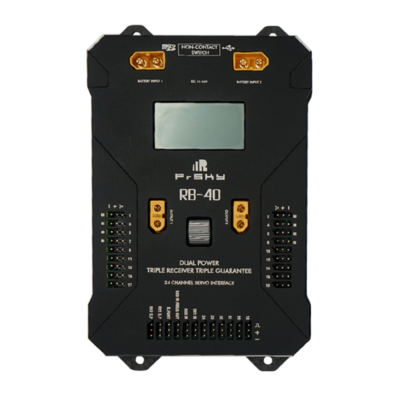
- Page 2 Introduction Overview The RB-30/RB-40 utilizes all the trusted attributes of the previous Redundancy Bus series along with adding new features to meet the needs of an ever-growing range of users. NON-CONTACT SWITCH The upgraded redundancy hub Previous redundancy bus models offered a dual-power with a dual-receiver design, the RB-30/RB-40 allows the user to use a triple redundancy by adding a multiplex port (RX3 IN / SBUS Out) and uses a set of standard XT30/XT60 plugs which provides a safe and efficient way to provide power.
-
Page 3: Specifications
* The RX3 IN can be switched to S.BUS OUT by the script or the Scroll button or the Freelink App. • BATTERY INPUT1&BATTERY INPUT2-connectors for batteries, supply power for RB-30/RB-40 and connected receivers. • OUTPUT1&OUTPUT2: SBEC OUTPUT, Continuous Current: 2*15A@5~8.4V (RB-30 ) / 2*30A@5~8.4V(RB-40) Note: Use voltage above 16.8V if you want to reach 30A@8.4V please. - Page 4 Channel Mapping: Ch 7 Curr 0.0A Vbat2 Powe: 0mAh 1. The RB-30/RB-40 PWM 1 outputs the RX1 CH1 in default, if RX1 CH1 is not normal, it will switch to output the RX2 CH1. Ch 8 Curr 0.0A Vout2 Volt: 0.1V...
- Page 5 CHn (n:17~24) overload RBS:indication of receiver status. Display Definition for Value RX OK normal All values above will be transmitted to FrSky radio system in real time AccX/Y/Z—Accelerometer triaxial parameter RXn_FS Receiver n Failsafe CH1A~CH8A—The current telemetry of CH1 ~CH8 RXn_LOSTFRAME...
- Page 6 Attention: CH1~CH8 should be connected to the corresponding servos. 1. RB-30/RB-40 doesn't support hotplug. When RX1 or RX2 is replaced halfway, RB-30/RB-40 needs to be repowered Set up your model and receiver 2. Make sure both of the receivers output the same signal. For example,when S8R and X8R are used together, disable Stab function on S8R, or they will output different signals.
- Page 7 (CH11 SW Down) (CH11 SW Up) (CH11 SW Mid) Note: The default mode of RB-30/RB-40 is Quick Mode.When re-flashing firmware of RB-30/RB-40 or replacing Delta wing & Flying wing & V-tail with a new one, the preset mode will be erased.
- Page 8 When Delta wing/Flying wing/V-tail is selected, the signal produced by the transmitter should be without active mixes on the Configuration channels related to AIL and ELE. RB-30/RB-40 will mix the AIL(CH1) and ELE(CH2) input signal with a fixed mix percentage Methods: APP configuration automatically.
- Page 9 RB30/RB40 PARAM Set RB30/RB40 Calibration FrSky radio LUA configuration (take RB-40 for example): • Copy the RB30/RB40.Lua files to the SD card of the transmitter • Bind the RX to the transmitter and run the files • RB30/40 STAB Set...
- Page 10 • RB30/40 PARAM Set • RB30/40 Calibration : Step 1. [Front side up] Open the script, follow the instructions, place RB30/40 on the front, and click OK. When the LED lights are flashing and the calibration is completed, click next step. Page 17 Page 18...
- Page 11 Page 19 Page 20...
- Page 12 Page 21 Page 22...
- Page 13 Step 2. [Front side down] Step 3. [Top side down] Page 23 Page 24...
- Page 14 Step 4. [Top side up] Step 5. [Right side up] Page 25 Page 26...
- Page 15 Step 6. [Right side down] * The LED should be pluged into CH24 port before calibration. The positive and negative values related to three-axis gyroscope and accelerometer make a total of six values that need to be acquired. Page 27 Page 28...
- Page 16 • Click the “Calibration” button and wait until the BLUE LED flashing, indicating the calibration on this orientation has been completed. • Repeat the above step five times (remaining 5 dimensions). Placing RB-30/RB-40 in the required orientation, ensure all values (X, Y, Z, Mod) are 1.000 with the deviation of ±0.1.
- Page 17 • Always install RB-30/RB-40 straight and level in the model. If required, PC software could be used to adjust the angle of to flight modes is correct and the compensation direction of the gyro is set as intended on AIL, RUD and ELE.
Need help?
Do you have a question about the RB-30 and is the answer not in the manual?
Questions and answers