
Related Manuals for FIBARO FGIC-002

Summary of Contents for FIBARO FGIC-002
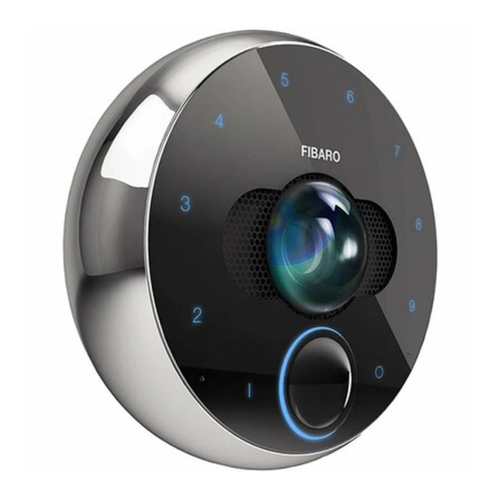
- Page 1 INTERCOM SMART VIDEO DOORBELL User manual for FGIC-002 Installation & Configuration Guide...
-
Page 3: Table Of Contents
1: Contents 1: Important safety information ............................4 2: Description and features ...............................5 2.1: Description ..........................................5 2.2: Main features ......................................... 5 3: Installation ..................................6 3.1: Package contents ........................................6 3.2: Required equipment ......................................7 3.3: Choosing location ......................................... 7 3.4: Choosing and routing wires .................................... -
Page 4: 1: Important Safety Information
2: Important safety information Read this manual before attempting to install the device! Failure to observe recommendations included in this manual may be dangerous or cause a violation of the law. The manufacturer, Fibar Group S.A. will not be held re- sponsible for any loss or damage resulting from not following the instructions of operating manual. -
Page 5: 2: Description And Features
3: Description and features 3.1: Description FIBARO Intercom can show you everyone who has arrived at your doorstep with a 180-de- gree high-definition view and night vision. This modern-looking, high-gloss device can be placed near the front door or gate to look after your safety. -
Page 6: 3: Installation
4: Installation Before installing the device: 1) Check if the package content is complete, 2) Prepare all the required equipment, 3) Make sure the power is off. 4.1: Package contents On-wall part In-wall part Installation box M2 x 8mm DIN913 hex 2.2mm x 12mm Hex key 0.9mm Tightening tool... -
Page 7: Required Equipment
4.2: Required equipment PH0 and PH1 Philips Needle-nose pliers Wire stripper Screwdrivers or Tweezers Remember that other professional equipment for mounting the installation box depends on the type of construction material. 4.3: Choosing location The device is rated at IP 54, which means it is protected against water splashed from all directions. -
Page 8: Choosing And Routing Wires
4.4: Choosing and routing wires The device may be powered in two ways: 1) Power supply 12V DC (+/- 10%) 1A LPS (not included) 2) PoE (Power over Ethernet) PSE 48V Both powering modes work in parallel and may be connected at the same time with no effect on the device operation. -
Page 9: Mounting The Installation Box
When routing wires take into consideration the following remarks: • The installation wires of the unit must be lead separately from the mains power wires to prevent the transmission interference and overvoltage on the control lines. • Wires inside the installation boxes should be as short as possible to prevent curling the wires and allow for easy assembling of the in-wall part. - Page 10 To install the box: 4) Mount the box in the hole and align it so 1) Prepare hole for 65mm x 75mm (diameter the TOP arrow points up. x depth) installation box. 2) Route cables to the back of the hole (see “Choosing and routing wires”...
-
Page 11: Mounting The In-Wall Part
4) Using three attached screws fasten the screw that secures the masking cap part with the box, make sure it is aligns properly and adjoins the wall. labelled with FIBARO logo. 2) Drag the wires through the hole located on the right of the in-wall part. -
Page 12: Connecting Wires
4.7: Connecting wires To connect the wires: 1) Make sure that no wires are powered. 6) Put the wires inside the terminals using 2) Remove the outer insulation to expose long-nose pliers or tweezers according to about 5 cm of the insulated inner wires, diagrams below. -
Page 13: Connecting Ethernet/Poe Cable
4.8: Connecting ethernet/POE cable: ETH1-ETH8 inputs are related to specified numbers of wires in RJ-45 connector according to the T-568B standard as shown below: 1) White Orange 2) Orange 3) White Green 4) Blue 5) White Blue 6) Green o O g B b G br BR 7) White Brown 8) Brown 4.9: Connecting 12V DC power supply:... -
Page 14: Connecting Relays
4.10: Connecting relays Connecting buttons for relays Configurable relay outputs 30V/1A R1 R1 R2 R2 N1 GND N2 Configurable dry contact logic inputs de- Outputs are not designed for long-term sup- signed to be operated by reed sensors, plying of external devices. Contacts are not switches, and relay outputs. -
Page 15: Mounting The On-Wall Part
4.12: Mounting the on-wall part To mount the on-wall part: 5) Using the included hex key, tighten the small hex screw until it flushes with 1) Install the masking cap and tighten it the black ring (look at the picture on with a screw. -
Page 16: Memory Card As Local Storage
4.13: Memory card as local storage The device allows for installing the microSD Card for local storage of recordings. FIBARO Intercom supports up to 64 GB microSDHC and microSDXC cards, 64 GB Class 10 is recommended. As for recording time, please check the chart below. -
Page 17: 4: First Time Configuration
• FIBARO ID account (which you can set up during the configuration process). Make sure that during the configuration of FIBARO Intercom your smartphone is connected to the same network as your device. During the setup be close to the device. -
Page 18: Logging In
5.2: Logging in 5.3: Creating home Having a valid FIBARO ID account is neces- In this step, it is possible to create a new sary to use your device. Such account may home or login to existing one. be created through the same app that is de- signed to work with the Intercom. -
Page 19: Network Configuration
5.4: Network configuration After selecting your Intercom from the list, you can establish a network connection. You can do this in three ways: via Wi-Fi, LAN (auto), LAN (manual). Wi-Fi connection Make sure that the range of Wi-Fi signal is good enough. If the Intercom is located far from Wi-Fi router, it is strongly recommended to use Wi-Fi signal expanders nearby the Intercom. -
Page 20: User Configuration
5.5: User configuration To configure a new user: User roles 1) Type in your name in provided form and There are three user roles available in FIBARO Intercom interface: tap Next. 2) Set your photo. You can choose it from Administrator - can configure home, •... -
Page 21: 5: Operating The Device
6: Operating the device 6.1: Opening the gate FIBARO Intercom allows to use rotating ring for entering PIN Codes set during the configuration process. Correctly entered PIN code may result in authenticating the user and opening the gate. Anyone who does not have a PIN code may use the button on the front to make a call. -
Page 22: Making A Call
To make a call: 3) Tap Invite User button. 1) Move your hand close to the device - the 4) Fill the FIBARO ID user’s e-mail address in button will light up in blue. the form. 2) Press the button. -
Page 23: Resetting To Factory Settings
6.4: Resetting to factory 6.5: Visual indications settings The Intercom is equipped with a LED Illumi- nated dial signaling device states, modes, There are two ways of performing the reset and errors. of the device: through the mobile app or di- rectly using the device. After completion, the When the numbers on the dial: Intercom will be restored to factory settings. -
Page 24: Adding Trusted Device
6.6: Adding trusted device 6.7: Adding another Intercom FIBARO Intercom can open connected re- lays automatically when trusted bluetooth In case of installation of several devices in devices gets nearby. your house, it is possible to add another de- vice to your home. -
Page 25: 6: Use Cases
7: Use cases 7.1: Opening the gate with electromagnetic lock through the app 12V GND N1 GND N2 TMP TMP R1 R1 R2 R2 12/24V 7.2: Opening the gate through the wall switch at your home or near the exit 12V GND N1 GND N2 TMP TMP R1 R1 R2 R2 12/24V... -
Page 26: Connecting External Alarm Device
7.3: Connecting external alarm device 12V GND N1 GND N2 TMP TMP R1 R1 R2 R2 ALARM SYSTEM 7.4: One switch for opening the wicket, another one for opening the gate 12V GND N1 GND N2 TMP TMP R1 R1 R2 R2 12/24V + - 230VAC 12/24V... -
Page 27: 7: Specification
8: Specification Power supply: 12V DC and/or 48V PoE DC supply parameters: 12V +/- 10%, 1A LPS PoE parameters (PSE): 36-57V, 350mA (802.3af, Class 0) Power consumption: up to 5W Conductor cross-section: 0.14 ... 0.34 mm² (AWG 26 ... AWG 22) Communication protocols: Ethernet 10/100BASE-TX, Wi-Fi a/b/g/n 2.4/5GHz, Bluetooth®... -
Page 28: 8: Regulations
(ii) DECODE AVC VIDEO THAT WAS ENCODED individual or entity. BY A CONSUMER ENGAGED IN A PERSONAL Fibaro and Fibar Group logo are trademarks ACTIVITY AND/OR WAS OBTAINED FROM A of Fibar Group S.A. VIDEO PROVIDER LICENSED TO PROVIDE AVC Wi-Fi is a registered trademark of Wi-Fi Alli- VIDEO. -
Page 29: 9: Warranty Terms And Conditions
NIP 7811858097, REGON: 301595664, share capital PLN 1,182,100 - the guarantee document is not valid or there is no proof of pur- paid in full, other contact information is available at: www.fibaro. com (hereinafter “the Manufacturer”) guarantees that the device chase, sold (hereinafter: “the Device”... - Page 30 © 2019 Fibar Group S.A. All rights reserved Made in Poland www.fibaro.com 105460510101...
Need help?
Do you have a question about the FGIC-002 and is the answer not in the manual?
Questions and answers