Table of Contents
Advertisement
Quick Links
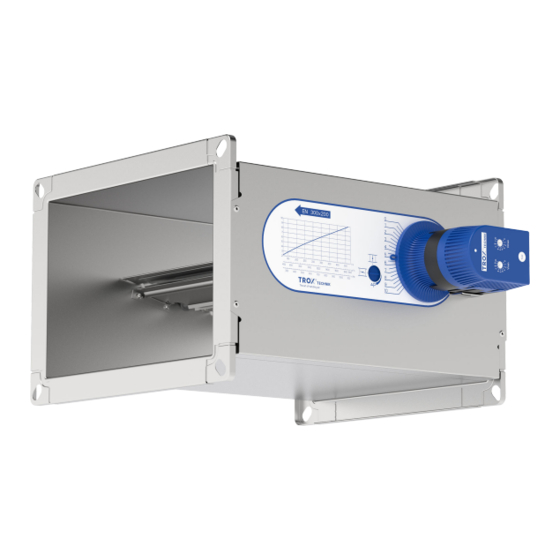
Product overview
Fig. 1: Air terminal unit type EN
1
Damper blade
2
Bellows
3
Bellows inlet
4
Scales sticker
5
Display damper blade position ðFig. 2
6
Hand wheel
7
Vmin-/Vmax actuator (optional)
Damper blade position display
The display is used to evaluate the throttle position
of the damper blade, e.g. in order to optimise the
control of the fan or the section regulation.
Attention: The display must not be adjusted.
Fig. 2: Display of the damper blade position
1
Damper blade in maximum throttle position -
Reduce system pressure
2
Damper blade in open position - System pres-
sure too low
Installation manual
CAV controllers
EN
CAV controllers EN
GB/en
Vmin-/Vmax actuator (optional)
Fig. 3: Vmin-/Vmax actuator
1
Vmax potentiometer
2
'Test' push button
3
Vmin potentiometer
4
LED status display
LED status display:
LED lit
LED flashes once per
second
LED flashes twice per
second
LED off
Functional test actuator
Press the test push button (> 2 s)
Actuator turns toward Vmin
ð
Actuator turns toward Vmax
Actuator returns to starting position
TROX GmbH
Heinrich-Trox-Platz
47504 Neukirchen-Vluyn
Germany
Phone: +49 (0) 2845 2020
Fax: +49 (0) 2845 202265
E-mail: trox@trox.de
http://www.troxtechnik.com
- Set position reached
- Actuator moves
- Actuator blocks
- No supply voltage
1
Advertisement
Table of Contents

Related Manuals for Trox Technik CAV controllers


Summary of Contents for Trox Technik CAV controllers
- Page 1 Damper blade in maximum throttle position - Actuator turns toward Vmin ð Reduce system pressure Actuator turns toward Vmax Damper blade in open position - System pres- sure too low Actuator returns to starting position CAV controllers EN...
-
Page 2: Important Notes
Correct use HVAC systems, understand any potential hazards CAV controllers of the type EN are used for con- related to the work under consideration, and recog- stant volume flow control in supply and extract air nise and avoid any risks involved. -
Page 3: Transport And Storage
If possible, take the product in its transport technical changes. packaging up to the installation location. Use only lifting and transport gear designed for the required load. Always secure the load against tipping and falling. CAV controllers EN... -
Page 4: Technical Data
Setpoint value – – 0 – 10 V signal input DC, Ra > 100 kΩ Actual value – – 0 – signal output 10 V DC, max. 0.5 m Ambient temper- 10-50 °C ature Ambient humidity 5-90% rF CAV controllers EN... - Page 5 500 × 200 500 × 250 500 × 300 500 × 400 14.5 500 × 500 15.5 600 × 200 600 × 250 10.5 600 × 300 11.5 600 × 400 600 × 500 600 × 600 CAV controllers EN...
- Page 6 500 × 200 500 × 250 14.5 500 × 300 15.5 500 × 400 20.5 500 × 500 600 × 200 15.5 600 × 250 16.5 600 × 300 600 × 400 600 × 500 600 × 600 27.5 CAV controllers EN...
-
Page 7: Installation
Observe airflow direction! Upstream conditions The volume flow rate accuracy of CAV controllers applies to a straight upstream section of the duct. Bends, junctions or a narrowing or widening of the duct cause turbulence that may affect volume flow rate measurement. -
Page 8: Installing The Controller
Be careful to not damage the controller accidentally: ding of the controller (on-site). Handle the unit with care. Lift the unit only by lifting the entire casing. Never lift the unit by the damper blade, rotary knob or actuator. CAV controllers EN... -
Page 9: Installation Instructions
– Pos. 0 Actuator has stopped (undefined posi- tion) The electrical connection to the actuator may open Pos. 2 Vmin only be made if the installation has been car- ried out correctly. Closed Pos. 3 Vmax CAV controllers EN... -
Page 10: Initial Commissioning
500 × 500 2380 1692 8568 Override control: With 24 VDC at terminal 3, the 600 × 500 2620 2160 9432 volume flow rate set at the Vmax potentiometer is 600 × 600 3500 2520 12600 started. CAV controllers EN... - Page 11 (Fig. 10/3). Carry out a functional test using the test No further measurement or adjustment is push button and check the scale position necessary. reached for the preset volume flow after the motorised adjustment process. CAV controllers EN...
- Page 12 Fig. 12: Characteristics of the control signal Scale setting Setpoint value w Vmin: 0 V ð scale setting 4.5 Vmax: 10 V ð scale setting 9 CAV controllers EN...
-
Page 13: Maintenance And Cleaning
Order code for retrofit kits: NR-VAV-EN-E01 24 V AC / DC actuator min / max switching NR-VAV-EN-E02 230 V AC / DC actuator min / max switching NR-VAV-EN-E03 24 V AC / DC constant actuator for variable operation CAV controllers EN... - Page 14 CAV controllers EN...
Need help?
Do you have a question about the CAV controllers and is the answer not in the manual?
Questions and answers