Table of Contents
Advertisement
Quick Links
Advertisement
Table of Contents

Related Manuals for Rockwell Automation MagneMotion NC-S


Summary of Contents for Rockwell Automation MagneMotion NC-S
- Page 1 NC Hardware User Manual Addendum, NC-S...
- Page 2 This product is protected under one or more U.S. and International patents. Additional U.S. and International patents are pending. Copyright © 2020 MagneMotion, Inc., a Rockwell Automation Company. All Rights Reserved. The information that is included in this document is proprietary or confidential to Rockwell Automation, Inc.
-
Page 3: Table Of Contents
NC Hardware User Manual Addendum, NC-S Contents About This Addendum ......................5 Purpose ..........................5 Audience ..........................5 Prerequisites ........................5 Reference Documents ......................5 Safety ............................6 Overview ..........................6 Regulatory Compliance ...................... 6 Safety Considerations ......................6 Symbol Identification......................7 Label Identification and Location .................. - Page 4 Transfer Log Files ......................28 Troubleshooting ........................ 29 Contact ICT Customer Support ..................30 Rockwell Automation Support ....................32 Figures Figure 1: Locations of Labels on the NC-S Node Controller ........... 7 Figure 2: NC-S Node Controller Mechanical Drawing ............14 Figure 3: NC-S Node Controller Electrical Connections, Controls, and Indicators ....
-
Page 5: About This Addendum
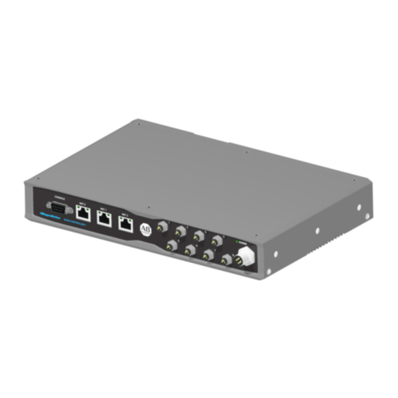
NC Hardware User Manual Addendum, NC-S About This Addendum This document is an addendum to the Node Controller Hardware User Manual and describes the NC-S node controller. The NC-S is a node controller with one active network port and eight RS-422 ports. This node controller supports multiple nodes (for example, Merge, Diverge, and Relay) using both RS-422 and Ethernet communication. -
Page 6: Safety
NC Hardware User Manual Addendum, NC-S Safety Overview This section describes safety guidelines for the NC-S node controller and its use in a transport system. All personnel that are involved in the operation or maintenance of the transport system must be familiar with the safety precautions that are described in this section. -
Page 7: Symbol Identification
NC Hardware User Manual Addendum, NC-S Symbol Identification See the Node Controller Hardware User Manual for all symbol identification and use information. Label Identification and Location Identification labels are placed on the node controllers. These labels provide operators and service personnel with information about the node controllers at the point of use. This section describes each label and identifies its location. -
Page 8: Electrical Hazards
NC Hardware User Manual Addendum, NC-S Electrical Hazards The MagneMotion node controllers are classified as low voltage devices, no additional safety precautions are required. The power supplies for the node controllers are connected to the AC Mains of the facility and can generate hazardous energy. -
Page 9: Recycling And Disposal Information
NC Hardware User Manual Addendum, NC-S Recycling and Disposal Information Information regarding disposal and recycling are provided in this section. The node controllers use the following items that require special handling for disposal or recycling. At the end of its life, this equipment must be collected separately from any unsorted municipal waste. -
Page 10: Node Controller Overview
NC Hardware User Manual Addendum, NC-S Node Controller Overview This document covers the NC-S, see the Node Controller Hardware User Manual for information that is related to all other node controller models. Node Controller Types All node controllers support Ethernet communication and, depending on the model, provide up to 12 RS-422 ports for communication with the motors. -
Page 11: Node Controller Communications
NC Hardware User Manual Addendum, NC-S Node Controller Communications System Communication All node controllers constantly communicate with the node controller configured as the HLC through a LAN. Additionally, the node controller that is designated as the HLC communicates with the host controller through the same network. All node controllers have the same IP address when they leave the factory. -
Page 12: Node Controller Loading
NC Hardware User Manual Addendum, NC-S Node Controller Loading When using RS-422 for motor communication, the load on the node controllers is physically limited by the number of nodes that can be connected to a node controller. When using Ethernet for motor communication, there is no physical limit to the number of nodes that are connected to the node controller. -
Page 13: Using Ethernet Communication
NC Hardware User Manual Addendum, NC-S Using Ethernet Communication When using Ethernet, the total load on the node controller is limited by the processing power of the node controller. Since there is no physical limit to the number of nodes that are connected to the node controller, connections must be limited based on the load they place on the processor as shown in Table 2. -
Page 14: Mechanical Specifications
NC Hardware User Manual Addendum, NC-S Mechanical Specifications All drawings within this document are generic and may not reflect specific configurations of the MagneMotion NC-S node controller. To obtain current drawings, contact Customer Support. NC-S 196.50 100.0 CABLE CONNECTOR EXCLUSION AREA 289.0... -
Page 15: Electrical Specifications
NC Hardware User Manual Addendum, NC-S Electrical Specifications NC-S Node Controller 24–48V DC ±10%, 10 W maximum based on configuration and operating mode. See Mechanical Specifications on page 30 for the mechanical drawing. DC Power The actual power being drawn depends on the operations being performed. Make sure that all power wiring can carry the full load and has a limited power source or the power source is fused to the maximum rating of the wiring. -
Page 16: Figure 3: Nc-S Node Controller Electrical Connections, Controls, And Indicators
NC Hardware User Manual Addendum, NC-S POWER CONSOLE NET 0 NET 1 NET 2 NODE CONTROLLER-S Network Console RS-422 (8X) Power Figure 3: NC-S Node Controller Electrical Connections, Controls, and Indicators Table 3: NC-S Node Controller Electrical Connections Label Description Connector Type CONSOLE External terminal... -
Page 17: Table 6: Nc-S Node Controller Console Pinout
NC Hardware User Manual Addendum, NC-S Table 6: NC-S Node Controller Console Pinout DE-9, Male — — — — — — Table 7: NC-S Node Controller Ethernet Pinout RJ45, Female — — — — MMI-UM035A-EN-P Page 17 of 32... -
Page 18: Table 8: Nc-S Node Controller Rs-422 Pinouts
NC Hardware User Manual Addendum, NC-S Table 8: NC-S Node Controller RS-422 Pinouts RJ45, Female RxD+ RxD- TxD+ TxD- MMI-UM035A-EN-P Page 18 of 32... -
Page 19: Environmental Requirements
NC Hardware User Manual Addendum, NC-S Environmental Requirements See the Node Controller Hardware User Manual for additional environmental requirements. NC-S Temperature: Operating: 0 °C to 50 °C [32 °F to 122 °F] Storage: -18 °C to 60 °C [0 °F to 140 °F] Humidity: 85% max (relative, noncondensing) MMI-UM035A-EN-P... -
Page 20: Installation
NC Hardware User Manual Addendum, NC-S Installation Unpacking and Moving The MagneMotion NC-S node controllers arrive from the factory as a component ready for final installation. The Node Controller Hardware User Manual provides the information that is required to unpack and install these components. -
Page 21: Din Rail Mounting
NC Hardware User Manual Addendum, NC-S DIN Rail Mounting The NC-S can be mounted to a DIN Rail by attaching the optional DIN rail mounting bracket as shown in Figure 288.8 95.0 21.8 51.4 183.0 43.5 Figure 5: NC-S Node Controller DIN Rail Mounting 1. -
Page 22: Surface Mounting
NC Hardware User Manual Addendum, NC-S Surface Mounting The NC-S can be mounted to a convenient surface by attaching the optional mounting bracket as shown in Figure 348.6 323.8 15.0 70.0 170.0 70.0 5.50 THRU HOLE 43.5 Figure 6: NC-S Node Controller Surface Mounting 1. -
Page 23: Upgrading From Nc-12 Or Nc Lite Node Controllers
NC Hardware User Manual Addendum, NC-S Upgrading from NC-12 or NC LITE Node Controllers This procedure provides the steps necessary to upgrade to NC-S node controllers from an NC-12. The NC-12 supports twelve RS-422 connections while the NC-S supports eight RS- 422 connections. -
Page 24: Configure And Connect The New Node Controllers
NC Hardware User Manual Addendum, NC-S Configure and Connect the New Node Controllers All node controllers in the system must be running the same software version. Therefore, when upgrading any node controller to the NC-S it is necessary to upgrade all other node controllers in the system to the same software version. - Page 25 NC Hardware User Manual Addendum, NC-S 7. Update the Node Controller Configuration File to reference the new node controllers if necessary (see Update the Node Controller Configuration File). 8. Upload the Node Controller Configuration File (see the Node Controller Interface User Manual).
-
Page 26: Update The Node Controller Configuration File
NC Hardware User Manual Addendum, NC-S Update the Node Controller Configuration File If the node controller being replaced had more than eight RS-422 connections, the Node Controller Configuration File must be updated to distribute those connections between two new NC-S node controllers. Typically, connections to ports 1–8 are connected to ports 1–8 of the first NC-S and connections to ports 9–12 are connected to ports 1–4 of the second NC-S. -
Page 27: Maintenance
NC Hardware User Manual Addendum, NC-S Maintenance The MagneMotion motors, node controllers, and power supplies are self-contained components that are designed for use in a clean, inert environment, and require no maintenance other than that described here. Any deviation from this basic environment can affect the maintenance requirements, contact ICT Customer Support for additional information. -
Page 28: Transfer Log Files
NC Hardware User Manual Addendum, NC-S Transfer Log Files Review the log files for each node controller and the high-level controller periodically to look for unexpected messages. Log files can be transferred from the node controller or SysLog server to a network server so they can be archived or e-mailed to ICT Customer Support, see the Node Controller Interface User Manual. -
Page 29: Troubleshooting
NC Hardware User Manual Addendum, NC-S Troubleshooting This section describes the common difficulties that can be encountered with the MagneMotion transport system and software components. For assistance, see Contact ICT Customer Support on page 30. Table 11: Troubleshooting Symptom Problem Description Corrective Action* Node controller logs do not The battery for the clock in the... -
Page 30: Contact Ict Customer Support
NC Hardware User Manual Addendum, NC-S Contact ICT Customer Support To help you receive the most value from the Rockwell Automation Independent Cart Technology (ICT) Support Specialists, have the following information ready before contacting ICT Customer Support. 1. The name, email address, and telephone number of the person to contact. - Page 31 NC Hardware User Manual Addendum, NC-S Revision History Rev. Change Description Initial release MMI-UM035A-EN-P Page 31 of 32...
-
Page 32: Rockwell Automation Support
Americas: Rockwell Automation, 1201 South Second Street, Milwaukee, WI 53204-2496 USA, Tel: (1) 414.382.2000, Fax: (1) 414.382.4444 Europe/Middle East/Africa: Rockwell Automation NV, Pegasus Park, De Kleetlaan 12a, 1831 Diegem, Belgium, Tel: (32) 2 663 0600, Fax: (32) 2 663 0640 Asia Pacific: Rockwell Automation, Level 14, Core F, Cyberport 3, 100 Cyberport Road, Hong Kong, Tel: (852) 2887 4788, Fax: (852) 2508 1846 Copyright ©...
Need help?
Do you have a question about the MagneMotion NC-S and is the answer not in the manual?
Questions and answers