Advertisement
Table of Contents
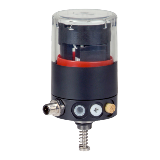
operating instructions position indicator type 024.63...
1.) Beschreibung:
Der Positionsanzeiger Typ 024.63...wurde für die
Rückmeldung der beiden Endlagen eines Ventils
entwickelt. Zur Rückmeldung der Stellungen offen und
geschlossen
sind
zwei
Subminiatur-Schalter integriert. Als Option können auch
Namur Sensoren (024.64...) oder 3 Draht PNP Sensoren
(024.65...) eingebaut werden. Durch die Klarsichthaube
ist die Hubstellung durch die integrierte, optische
Sichtanzeige erkennbar. Innovativ sind die sich selbst
einstellenden Schaltnocken. Diese legen sich beim 1.
Hub der Armatur an die jeweilige Endstellung an. Eine
Einstellung der Schaltnocken ist nicht mehr erforderlich,
eine Beschädigung beim Überfahren der Schalter mit
dem Schaltnocken ist ausgeschlossen. Sie ist so
ausgeführt, daß sie auf alle fremdgesteuerten SED
Armaturen paßt. Der elektrische Anschluß erfolgt über
einen Mehrpol – Stecker, als Option sind andere
Anschlußmöglichkeiten möglich.
Nr.
Teilebezeichnung
Part description
1
Schutzhaube
protective cap
2
Halter
connection
3
Sichtanzeige
position indicator
4
Grundhalter
ground connection
6
Schraube
screw
7
Adapter
connection
8
Distanz Hülse
distance ring
9
Spindel
spindle
10
Schaltnocken #3
switch cam #3
13
Schraube
screw
17
Abdeckplatte
plate
18
mont. Schalter
assembled switcher
19
Distanzstück
distanze piece
20
Kabelverbinder
cable connector
Führung
guide
26
Gewindestift
grub screw
27
O-Ring
o-ring
28
O-Ring
o-ring
32
34
Kabelstecker
cable coupling
Klebstoff
glue
37
2.) Allgemeine Sicherheitshinweise
ACHTUNG - VORSICHT BEI HANDHABUNG!
ELEKTROSTATISCH GEFÄHRDETE BAUELEMENTE / BAUGRUPPEN
SCHUTZ GEGEN BESCHÄDIGUNG DURCH ELEKTROSTATISCHE
AUFLADUNG
Die Platine enthält elektronische Bauelemente, die auf elektrostatische
Entladung
(ESD)
empfindlich
aufgeladenen Personen oder Gegenständen gefährden diese Bauelemente.
Im schlimmsten Fall werden sie zerstört oder fallen nach der Inbetriebnahme
aus. Beachten Sie die Anforderungen nach EN 100 015 - 1, um die
Möglichkeit eines Schadens durch schlagartige elektrostatische Entladung zu
minimieren bzw. zu vermeiden. Achten Sie ebenso darauf, dass Sie
elektronische Bauelemente nicht bei anliegender Versorgungsspannung
berühren.
Achtung:
Die elektrischen Anschlußwerte dürfen auf keinen Fall überschritten werden.
Die Inbetriebnahme darf nur von geschultem Fachpersonal unter Beachtung
dieser Betriebsanleitung durchgeführt werden. Die Steuereinheit darf nur in
der Originalverpackung transportiert werden.
Für Beschädigungen, die durch unsachgemäßes Betreiben des Gerätes an
der Schalterplatine (Pos. 18) oder an dem Kabelstecker (Pos. 34) entstehen,
erlischt jegliche Haftung unsererseits.
HENRICUSKADE 119A
Betriebsanleitung Positionsanzeiger Typ 024.63...
Änderungen vorbehalten - subject alteration
mechanisch
arbeitende
Pcs.
Material / Material
1
Polysulfon
1
PP 30% Gf – schwarz / black
1
PVDF – rot / red
1
POM
3
St. Steel
1
1.4104 – st. steel
1
1.4305
1
1.4305 – st. steel
2
PBTB + Stahl / steel
3
st. Steel
1
geklebt (stick with glue)
1
1
PVC
6
Ms/PVC
2
EP
2
st. Steel
2
NBR (60x3)
1
1
NBR (21x2)
1
reagieren.
Kontakt
mit
elektrostatisch
|
2497 NB THE HAGUE
|
Artikel Nr / Part code
00103.2489.401
00115.2463.001
00102.2489.002
00115.2463.002
00292.099.2.2.6.5 VA
00255.2489.MXX.X
00255.2499.0XX
00255.2489.XXX
00102.2489.501
00292.099.2.2.9.5VA
00103.2463.001
00103.2489.505
00130.2489.005
00313.2463.001
00300.000.0505.2
00289.099.4.10 VA
00202.2489.60.3
00202.997.21.2
00311.2463.001
00660.010.01
#3 = unterer Nocken Metal nach oben, oberer Nocken Metal nach unten
#3 = cam bottom metal to top, top cam metal to bottom
2.) General Safety Information
ELECTROSTATIC SENSITIVE COMPONENTS / MODULES
PROTECTION AGAINST DAMAGE BY ELECTROSTATIC CHARGE
The board contains electronic components that react sensitive to
electrostatic discharge (ESD). Contact with electrostatically charged
persons or objects are hazardous to these components. In the worst
case they are destroyed or fail after implementing. Observe the
requirements of EN 100 015 - 1 in order to minimize or avoid the
possibility of damage caused by sudden electrostatic discharge. Also
ensure that you do not touch electronic components when voltage is
supplied.
Caution:
The power values must not be exceeded under any circumstances.
Implementing may only be carried out by qualified personnel in
accordance with these instructions. The control unit must be
transported in its original packaging.
We do not accept any liability for damages at the switch board (item
18) or on the cable plug (item 34) caused by improper operation of the
unit.
THE NETHERLANDS
|
T +31 (0)85 043 31 10
BA/BA03_0007_024_63...doc
1.) Description
The electrical control head is made to signal
the final positions of a valve. To signal the
open or closed position, 2 mechanical
subminiature switches are integrated. The
control head is also available with Namur
sensors (024.64...) or 3-wire PNP sensors
(024.65...)
The transparent cover provides a good view
on the integrated. optical position indicator.
Also innovative are the self-adjusting switch
cams, which are adjusted automatically with
the first valve stroke. A manual adjustment is
no longer required and a damage caused by
overtraveling the switches isn't possible.
The control head is designed to fit on all
pneumatically operated SED actuators.
The electrical connection is made by a
multipol-plug. There are also other types of
connections available as an option.
ATTENTION - CAUTION ON HANDLING!
|
E INFO@ROMYNOX.NL
|
I WWW.ROMYNOX.NL
BA 03 0007
Rev. g Seite 1 von 3
05.02.13 – MA/PJ
Advertisement
Table of Contents

Summary of Contents for SED flowcontrol 024.63 Series
- Page 1 BA 03 0007 Betriebsanleitung Positionsanzeiger Typ 024.63... Rev. g Seite 1 von 3 operating instructions position indicator type 024.63... 05.02.13 – MA/PJ BA/BA03_0007_024_63...doc Änderungen vorbehalten - subject alteration 1.) Beschreibung: 1.) Description Der Positionsanzeiger Typ 024.63...wurde für die The electrical control head is made to signal Rückmeldung der beiden Endlagen eines Ventils the final positions of a valve.
- Page 2 BA 03 0007 Betriebsanleitung Positionsanzeiger Typ 024.63... Rev. g Seite 2 von 3 operating instructions position indicator type 024.63... 05.02.13 – MA/PJ BA/BA03_0007_024_63...doc Änderungen vorbehalten - subject alteration 3.) Technische Daten 3.) Technical Data Schaltertyp Mikroschalter type micro switch mech. Lebensdauer 10 000 000 mec.
- Page 3 BA 03 0007 Betriebsanleitung Positionsanzeiger Typ 024.63... Rev. g Seite 3 von 3 operating instructions position indicator type 024.63... 05.02.13 – MA/PJ BA/BA03_0007_024_63...doc Änderungen vorbehalten - subject alteration 5.) Montage 5.) Assembly 1.) Bitte lesen Sie zuerst diese Betriebsanleitung sorgfältig durch. 1.) Please read this manual carefully.
Need help?
Do you have a question about the 024.63 Series and is the answer not in the manual?
Questions and answers