Table of Contents
Advertisement
Advertisement
Table of Contents

Related Manuals for Hirschmann HC3901


Summary of Contents for Hirschmann HC3901
- Page 1 HIRSCHMANN Load Moment Indicator for Crawler Crane HC3901 Operator’s Manual Hirschmann Electronics(Shanghai)Co.,Ltd Suite 12A, Huamin Empire Plaza, No.726, West Yan An Road, Shanghai, P.R.China Tel: 021-51082780 Fax: 021-52375899 Zipcode: 200050 Website: http://www.hirschmann.com...
- Page 2 Declaration All information in this document is subject to change without notice. Hirschmann makes no warranty of any kind with regard to this material, including, but not limited to, the implied warranties of merchantability and fitness for a particular purpose.
-
Page 3: Table Of Contents
Table of Contents 1. GENERAL INFORMATION ........................1 2. IMPORTANT NOTES ..........................2 3. SYSTEM DESCRIPTION ......................... 3 3.1 HC3901 Controller ..........................4 3.2 WG Angle Sensor ..........................5 3.3 Force Sensor............................6 4. OPERATION AND DISPLAY INTERFACE ..................7 4.1 Data display(values are only for example)... -
Page 4: General Information
1. GENERAL INFORMATION The load moment indicator HC3901 (hereinafter referred to as LMI) is applicable to the telescopic boom crane, lattice boom crane, all- terrain crane and other types of cranes. The HC3901 LMI can provide the crane operator with essential information required to operate the crane within its design parameters. -
Page 5: Important Notes
The pulse may cause damage to the electrical and electronics parts. Hirschmann shall not be liable for any damage caused by this. Make sure to disconnect the power supply of the LMI during thunderstorm weather. Hirschmann shall not be liable for any damage caused by lightning. -
Page 6: System Description
3. SYSTEM DESCRIPTION Components of LMI System Generally, the LMI system consists of 1. HC3901 Controller 1 pc 2. WG103 Angle Sensor 1 pc 3. KMD force Sensor 1 pc... -
Page 7: Hc3901 Controller
Operator’s Manual 3.1 HC3901 Controller HC3901 controller uses 16 bit high performance processors and the CANopen communication technology. It is the safety protector specially designed to meet the required safety standards under the harsh environment. Technical data: Operating temperature: –20°C ~ +70°C. -
Page 8: Wg Angle Sensor
3.2 WG Angle Sensor Angle sensor WG accurately measures the boom angle. The high sealed housing keeps the inside component away from the influence of temperature, humidity etc. Technical data Measuring range: 0-90° Output signal: 4-20mA Linearity tolerance: <±0.2° Hysteresis tolerance: <±0.1° Operating temperature: -25 ~+70 Storing temperature: -40 ~+70 Protection class: IP65... -
Page 9: Force Sensor
Operator’s Manual 3.3 Force Sensor Force sensor KMD is perfectly designed for static and dynamic tensile force measurements. The sensor stands out for high overload capacity, high fatigue strength, good corrosion resistance and maintenance-free operation. Technical data: Nominal load range: from 1T up to 500T Charge of measuring body: 200% Charge of measuring body up to flow limit: 300% Safe to breaking point: 500%... -
Page 10: Operation And Display Interface
4. OPERATION AND DISPLAY INTERFACE 1.Data display(see 4.1) 2.Indicator light 3.Function keys: from left to right, menu key/buzzer key/back key/confirmation key.(the function keys have one-to-one relationships with the key symbols on the display.) 4.Rotary button:They can be used to select function items on the display by rotating the button and confirm the selection by pushing the button. -
Page 11: Data Display(Values Are Only For Example
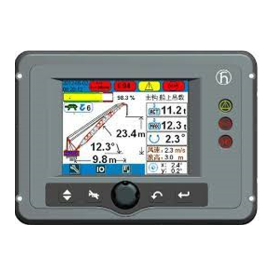
Operator’s Manual 4.1 Data display(values are only for example) 1. Height status bar and percentage display 11. Error code information key symbol 2. Jib angle 12. Upper and low angle setting 3. Jib length 13. Main Hook/ Subhook Switch 4. Height 14. -
Page 12: En13000
4.2 EN13000 The yellow icon is force-active warning icon: when the crane is forced to be active, corresponding warning icon will display on the main interface to remind that the crane is at force-active state now and LMI will not have corresponding protection function. LMI override activated Main hoist three times protection alarm SET-UP mode activated... -
Page 13: Weight Status Bar
Operator’s Manual 4.3Weight status bar The weight percentage status bar indicates the relationship between the actual load weight and the rated load weight during the crane operation and the weight percentage value is subject to the relationship changes. Green zone: safe range (weight percentage0-90%)... -
Page 14: Operation Method And Process (Only For Example)
5. OPERATION METHOD and PROCESS (only for example) When controller and console of the system is powered on, the data initialization automatically starts. This progress cannot be directly observed, but a welcoming display (Logo display) will appear at the console to present the manufacturer and the initializing status. The crane drivers shall be very familiar with the operation of LMI system and correctly adjust it before start to work. -
Page 15: Reeving Setting
Operator’s Manual 5.1 Set OM and Reev Reeving setting is to set the LMI reeving identical to the actual reeving.Operators shall carefully adjust the displayed reeving equal to the actual reeving before start to work. WARNING The Reeving must be set equal to the actual reeving, otherwise the LMI may not be able to work properly. At the main display, select icon by rotary button, press it or confirmation key to enter into “Set OM and Reev”... -
Page 16: Function Setting
Two switchable OMs can be selected by default OM option. 5.2 Function Setting At the main display, select icon by rotate button, press the button or confirmation key to enter into ”Function Page” as followed: Back to the previous display. Confirm the select value. - Page 17 Operator’s Manual Time Setting Before setting time, the first step is to input the password. If the display shows the wrong time, please connect with the manufacture first. DO NOT set time yourself. The setting steps are as followed: At first, select “Time Set” icon by rotating button at the “Function Display”, press the button or confirmation key to enter into “Input Password”...
- Page 18 5.2.2 CANbus Status Overview At the “Function Display”, select “Can Bus” icon by rotary button, press it or confirmation key to enter into ”CANbus Status Overview Display” as followed: Back to the previous display. Confirm the select value. Back to the main display. At this display: If the pane shows green, it means working normally.
- Page 19 Operator’s Manual Back to the previous display. Back to the main display. 5.2.4 Load Inquriy At the “Function Display”, select “Load Chart” icon by rotary button, press it or confirmation button to enter into the “OM select” display: Back to the previous display. Confirm the select value.
-
Page 20: Error Code Information
5.3 Error Code Information When the system appears malfunction, the error code would appear at the main display.Through the error code information, crane operators and service engineers can better understand what the error code stands for, and quickly find out the fault reasons and suggested solutions. (Operators can inquire the error code by two ways: The error code inquiry in the display and the “troubleshooting”... -
Page 21: System Functions
Operator’s Manual 6. SYSTEM FUNCTIONS 6.1 Warning Under any below conditions, HC3901 LMI system will light up and send out alarm for warning. The crane is overload The hook approaching height limitation System error 6.2 Prohibition Cooperating with crane electrics system, the LMI system will send alarm warning and any of the following crane’s movements will be prohibited:... -
Page 22: Inspection Maintenance And Considerations
7 INSPECTION MAINTENANCE AND CONSIDERATIONS 7.1 Inspection before Operation Check all components of the LMI system to make sure no one damages or breaks off. Turn the power on and detect whether the display is normal or there is warning, error indication and so on. -
Page 23: Troubleshooting
If the errors cannot be solved by following the instruction in the table, please contact our service team: Tel: +86-400-887-9936 Fax: +86-516-87793971 Email: infoecs@hirschmann-js.com Error Error Cause Elimination Code ... - Page 24 Error Error Cause Elimination Code Fallen below lower Cable between the central unit Check cable as well as plugs, limit value force transducer replace, if need be measuring channel defective or loose. Water "force main inside plug boom(MB) right" transducer ...
- Page 25 Operator’s Manual Error Error Cause Elimination Code Fallen below lower Cable between the central unit Check cable as well as plugs, limit value and the pressure transducer replace, if need be measuring channel defective or loose. Water "MB backstip inside plug...
- Page 26 Error Error Cause Elimination Code Upper limit value in refer to E14 refer to E14 measuring channel "force main boom left" been exceeded. Upper limit value in refer to E15 refer to E15 measuring channel "main boom angle foot"...
- Page 27 Operator’s Manual Error Error Cause Elimination Code Error in the logical System Upload valid system software program file program flow Replace central unit defective Flash-EPROM defective The system program in the Upload valid system program System program and crane data file do not LMI does not match to the...
- Page 28 Error Error Cause Elimination Code Too large difference The angle as to the horizontal Check angle sensor on the jib luffing on the jib head exceeds the head. angles at tip and base luffing jib angle by more than ...
- Page 29 Operator’s Manual Error Error Cause Elimination Code Fallen below lower No rope on the winch calibrate rope length limit value mount (* only EB1) sensor disable measuring channel No sensor winch function in data-programming "rope length on the measuring available ...
Need help?
Do you have a question about the HC3901 and is the answer not in the manual?
Questions and answers