Table of Contents
Advertisement
Available languages
Available languages
Quick Links
D
IP-Kamera,
20-2906A-IP/21-2906A-IP, 20-2913A-IP/21-2913A-IP,
43-9582, 43-9588, 50-2906A-IP
GB IP camera,
20-2906A-IP/21-2906A-IP, 20-2913A-IP/21-2913A-IP,
43-9582, 43-9588, 50-2906A-IP
F
Caméra IP,
20-2906A-IP/21-2906A-IP, 20-2913A-IP/21-2913A-IP,
43-9582, 43-9588, 50-2906A-IP
Achtung: Techn. Änderung zu den Seiten 4/5
Attention: Techn. change to the pages 18/19
Attention : Techn. changer les pages 32/33
Firmwares AXIS M3045 > = 7.20.1.
Firmwares AXIS M3007 > = 6.30.1
anleitung
Version 3.5
Seite .... 3
Page .... 17
Page .... 31
Advertisement
Chapters
Table of Contents

Related Manuals for Telecom Behnke 20-2906A-IP


Summary of Contents for Telecom Behnke 20-2906A-IP
- Page 1 Attention : Techn. changer les pages 32/33 Firmwares AXIS M3045 > = 7.20.1. Firmwares AXIS M3007 > = 6.30.1 anleitung Version 3.5 IP-Kamera, 20-2906A-IP/21-2906A-IP, 20-2913A-IP/21-2913A-IP, 43-9582, 43-9588, 50-2906A-IP Seite ..3 GB IP camera, 20-2906A-IP/21-2906A-IP, 20-2913A-IP/21-2913A-IP, Page ..17 43-9582, 43-9588, 50-2906A-IP Caméra IP,...
- Page 2 Wartungs- oder Reparaturarbeiten vom Stromnetz (Steckernetzteil) und vom Netzwerk bzw. Telefonanschluss getrennt sind und die einschlägigen Sicherheitsregeln eingehalten werden. Weitere rechtliche Hinweise finden Sie auf Seite 14. KontaKt Info-Hotline Telecom Behnke GmbH Ausführliche Informationen zu Produkten, Gewerbepark „An der Autobahn“ Projekten und unseren Dienstleistungen: Robert-Jungk-Straße 3...
-
Page 3: Table Of Contents
Anleitung IP-Kamera Inhalt inhalt 1. Einleitung 1.1. Lieferumfang ........................4 1.2. Allgemeines ........................4 ▸ Leistungsmerkmale ......................4 ▸ Kameraposition bestimmen ....................4 ▸ Videostream abrufen ......................5 1.3. IP-Kameramodul ......................6 1.4. IP-Hinterbaukamera ......................6 1.5. Anschluss IP-Kamera ......................7 ▸ LAN-Anschluss........................7 ▸ Stromversorgung ......................7 2. -
Page 4: Einleitung
„Kamerablende“ den Licht- die Kamera über einen LED-Beleuchtungsring einfall in die Kamera reduzieren und die Leistung (20-2906A-IP / 21-2906A-IP, 43-9588 / des Bildsensors herabsetzen wird. Daher 50-2906A-IP) für den Einsatz in schlecht sollten Sie die Kamera so positionieren, dass beleuchteten Bereichen. -
Page 5: Videostream Abrufen
Anleitung IP-Kamera Einleitung Videostream abrufen Systemvoraussetzung Kamera: Der AXIS-Kameratyp M3045 unterstützt den AXIS-Firmwarestand 7.20.1. und ist nur mit Um den Videostream in einem Browser abzu- diesem zu betreiben. rufen, geben Sie z. B. folgende URL ein: „http://<Benutzer>:<Passwort>@<ip-addr>/ Der AXIS Kameratyp M3007 unterstützt den axis-cgi/mjpg/video.cgi?resolution=1920x1080“... -
Page 6: Ip-Kameramodul
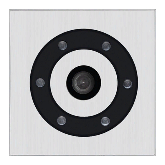
Anleitung IP-Kamera Einleitung 1.3. IP-Kameramodul 1.4. IP-Hinterbaukamera 20-2913A-IP 21-2913A-IP 43-9582 20-2906A-IP 21-2906A-IP 43-9588 Kameralinse Dome Beleuchtungsring mit weißen LEDs 50-2906A-IP (LEDs dauer an im Auslieferungszustand) www.behnke-online.de... -
Page 7: Anschluss Ip-Kamera
Serie 20 IP betrieben, erfolgt die Stromversor- gung der Kamera mittels PoE über die IP-Basise- lektronik. Beleuchtungsring Kameras mit Beleuchtungsring (20-2906A-IP, 21-2906A-IP, 43-9588 und 50-2906A-IP) verfügen über ein zusätzliches Anschlusskabel Seite 8 + 9) zur Stromversorgung des Beleuchtungsrings. Dieser kann ständig mit Strom versorgt werden. - Page 8 Anleitung IP-Kamera Einleitung LED-Beleuchtungsring der Kamera dauerhaft eingeschaltet Basiselektronik IP Input Output Kameramodul Rückseite LAN-Kabel (inkl. PoE zur Kamera) Anschlusskabel zur Stromversorgung des Beleuchtungsrings www.behnke-online.de...
- Page 9 Anleitung IP-Kamera Einleitung LED-Beleuchtungsring der Kamera im Aus- lieferungszustand nur während des Gesprächs eingeschaltet. Basiselektronik IP Input Output Kameramodul Rückseite LAN-Kabel (inkl. PoE zur Kamera) Anschlusskabel zur Stromversorgung des Beleuchtungsrings Die Aktivierung des Beleuchtungsrings ist von der Konfiguration der Betriebsart für Relais 2 in der SIP-Sprechstelle abhängig.
-
Page 10: Konfiguration Und Inbetriebnahme
Anleitung IP-Kamera Konfiguration und Inbetriebnahme Konfiguration und inbetriebnahme 2.1. Vorbereitung 2.3. Benutzername und Passwort ▸ Verbindung der IP-Videokamera mit einem Benutzername: root 100 Mbit Ethernet LAN Passwort: Admin ▸ Stromversorgung via Power over Ethernet (PoE) 2.4. Videostream per Browser abrufen Verbindung über Ethernet Videostream abrufen: Die IP Kamera ist im Standard als DHCP-Client... -
Page 11: Reset Auf Werkseinstellungen
(ca. 15 - 30 Sekunden) ▸ 3. HTTP/RTSP Password Settings: unencrypted only Folgende Einstellungen sind nach dem Reset unbedingt wieder durchzuführen: Bei 20-2906A-IP/21-2906A-IP/43-9588/ Diese Einstellungen sollten nur 20-2913A-IP/21-2913A-IP/50-2906A-IP: durchgeführt werden wenn ausrei- ▸ 1. Kamera Passwort vergeben chend Kenntnisse des AXIS-Webfront- ▸... -
Page 12: Technische Daten
Anleitung IP-Kamera Technische Daten technische daten 20-2906A-IP/21-2906A-IP, 20-2913A-IP/ 43-9582 21-2913A-IP/43-9588/50-2906A-IP Ausstattung ▸ Ausstattung Stromversorgung via PoE ▸ Stromversorgung via PoE (siehe „Stromversor- ▸ Digitaler PTZ gung“ auf Seite 7) ▸ ONVIF Kompatibel zum Einsatz mit Video- ▸ LED Beleuchtungsring überwachungssystemen unterschiedlicher ▸... -
Page 13: Bemaßung
Anleitung IP-Kamera Bemaßung bemassung Hinterbau (43-9582 / 43-9588) Frontalansicht Seitenansicht Ø 65 Wir empfehlen einen Hohlraumauschnitt von Bei der Kamera 43-9588 ist eine 120 x 120 x 40 mm (H x B x T) Plexi glasscheibe verbaut – kein Dom Elektromagnetische Verträglichkeit Niederspannungsrichtlinie... -
Page 14: Rechtliche Hinweise
Anleitung IP-Kamera Rechtliche Hinweise rechtliche hinweise Infos zum Produkthaftungsgesetz: 1. Änderungen an unseren Produkten, die dem technischen Fortschritt dienen, behalten wir uns vor. Die abgebildeten Produkte können im 1. Alle Produkte aus dieser Anleitung dürfen nur Zuge der ständigen Weiterentwicklung auch für den angegebenen Zweck verwendet werden. - Page 15 Attention : Techn. changer les pages 32/33 Firmwares AXIS M3045 > = 7.20.1. Firmwares AXIS M3007 > = 6.30.1 instructions Version 3.5 IP-Kamera, 20-2906A-IP/21-2906A-IP, 20-2913A-IP/21-2913A-IP, 43-9582, 43-9588, 50-2906A-IP Seite ..3 GB IP camera, 20-2906A-IP/21-2906A-IP, 20-2913A-IP/21-2913A-IP, 43-9582, 43-9588, 50-2906A-IP Page ..17 Caméra IP,...
- Page 16 (unplug power supply unit) and are disconnected from any other network and that all relevant safety regulations will be maintained. For further legal information, please see page 23. contact Information Telecom Behnke GmbH For detailed information on our product, Gewerbepark “An der Autobahn” projects and services: Robert-Jungk-Straße 3...
- Page 17 IP camera Instructions Contents contents 1. Introduction 1.1. What’s in the box ......................18 1.2. General Information ......................18 ▸ Features ......................... 18 ▸ Determining the camera position ..................18 ▸ Accessing the video feed ....................19 1.3. IP camera module ......................20 1.4.
-
Page 18: Introduction
The camera is also equipped with an into the camera and consequently will reduce LED illumination (20-2906A-IP / 21-2906A-IP, the image sensor performance. Therefore, try to 43-9588 / 50-2906A-IP) for use in poorly lit have the sun behind the camera when choos- areas. -
Page 19: Accessing The Video Feed
IP camera Instructions Introduction Accessing the video feed System requirement camera: The camera type AXIS M 3045 supports the AXIS firmware release 7.20.1. and is only to To access the video feed via a web browser, operate with this. please use the following URL: “http://<user>:<password>@<ip-addr>/axis-cgi/ The camera type AXIS M 3007 supports the mjpg/video.cgi?resolution=1920x1080”... -
Page 20: Ip Camera Module
IP camera Instructions Introduction 1.3. IP camera module 1.4. IP reverse side camera 20-2913A-IP 21-2913A-IP 43-9582 20-2906A-IP 21-2906A-IP 43-9588 Camera lens Dome Illumination with white LEDs 50-2906A-IP (LEDs permanently turned on in default settings) www.behnke-online.com... -
Page 21: Connecting The Ip Camera
, power for the camera is supplied via PoE from the IP basic electronics. Illumination Cameras featuring illumination (20-2906A-IP, 21-2906A-IP, 43-9588 and 50-2906A-IP) are equipped with an additional cable page 22 + 23) to supply power for the illumination unit. Continuous power supply is possible. - Page 22 IP camera Instructions Introduction Camera LED illumination permanently turned on IP basic electronics Input Output Camera module, rear view Network cable (including PoE to camera) LED illumination power supply cable www.behnke-online.com...
- Page 23 IP camera Instructions Introduction Camera LED illumination default setting: only turned on during a call. IP basic electronics Input Output Camera module, rear view Network cable (including PoE to camera) LED illumination power supply cable Turning on the LED illumination depends on the operations mode set for relay 2 of your SIP door intercom.
-
Page 24: Configuration And Set-Up
IP camera Instructions Configuration and set-up configuration and set-up 2.1. Preparation 2.3. User name and password ▸ Connect the IP camera to a 100 Mbit User name: root Ethernet LAN Password: Admin ▸ Power supply via Power over Ethernet (PoE) 2.4. -
Page 25: Reset To Default Settings
- 30 seconds), you may let go of the key ▸2.Powerline frequency: 50 Hz. ▸3. HTTP/RTSP Password Settings: The following settings must be performed unencrypted only again after the reset: (only 20-2906A-IP/21-2906A-IP/43-9588/ These settings should only be 20-2913A-IP/21-2913A-IP/50-2906A-IP) carried out if sufficient knowledge ▸ 1. Assign camera password of the AXIS web frontend is ▸... -
Page 26: Technical Specifications
IP camera Instructions Technical Specifications technical specifications 20-2906A-IP/21-2906A-IP, 20-2913A-IP/ 43-9582 21-2913A-IP Features ▸ Features Power supply via PoE ▸ Power supply via PoE (please cf. “Power ▸ Digital PTZ supply” on page 21) ▸ ONVIF compatibility to use with video surveil- ▸... -
Page 27: Dimensions
IP camera Instructions Dimensions dimensions Reverse side mounting (43-9582 / 43-9588) Front view Side view Ø 65 We suggest a cavity size of 120 x 120 x 40 mm The camera 43-9588 has a plexiglass (HxWxD) disc – no dome Electromagnetic Compatibility Low Voltage Directive All our products meet the standards for CE certification valid in the entire EU: Electro-... -
Page 28: Legal Information
IP camera Instructions Legal Information legal information Information with regard to product liability: 1. We reserve the right to change our products, without notice, for technical progress. As a result of continuous development, the products 1. All products mentioned in these instructions illustrated may look different from the products may only be used for the purpose intended. - Page 29 Attention : Techn. changer les pages 32/33 Firmwares AXIS M3045 > = 7.20.1. Firmwares AXIS M3007 > = 6.30.1 notice Version 3.5 IP-Kamera, 20-2906A-IP/21-2906A-IP, 20-2913A-IP/21-2913A-IP, 43-9582, 43-9588, 50-2906A-IP Seite ..3 GB IP camera, 20-2906A-IP/21-2906A-IP, 20-2913A-IP/21-2913A-IP, 43-9582, 43-9588, 50-2906A-IP Page ..17 Caméra IP,...
- Page 30 électrique (bloc d'alimentation), informatique et téléphonique et respec- ter les règles de sécurité en vigueur. Vous trouverez des informations légales complémentaires sur la page 42. contact Infoligne Telecom Behnke S.à r.l. Pour des informations détaillées 1, Avenue Saint Rémy concernant nos produits, projets et nos F-57600 Forbach services :...
- Page 31 Notice caméra IP Sommaire sommaire 1. Introduction 1.1. Étendue de la livraison ......................32 1.2. Généralités ........................32 ▸ Caractéristiques de fonctionnement ................32 ▸ Ajuster la position de la caméra ..................32 ▸ Récupérer le flux vidéo ....................33 1.3. Module caméra IP ......................34 1.4.
-
Page 32: Introduction
De plus, la caméra dis- blement influencer la qualité de l’image lors de la pose d’un anneau d’éclairage (20-2906A-IP / mise en service. Il est important d’éviter la lumière 21-2906A-IP, 43-9588 / 50-2906A-IP) LED pour directe provenant du soleil puisque les « dia-... -
Page 33: Récupérer Le Flux Vidéo
Notice caméra IP Introduction Récupérer le flux vidéo Caméra de l’exigence système: Le type de caméra AXIS M 3045 prend en charge la version du firmware AXIS 7.20.1. et est Afin d’afficher le flux vidéo dans un navigateur, seulement pour fonctionner avec cela. entrez par ex. -
Page 34: Module Caméra Ip
Notice caméra IP Introduction 1.3. Module caméra IP 1.4. Caméra IP arrière 20-2913A-IP 21-2913A-IP 43-9582 20-2906A-IP 21-2906A-IP 43-9588 Lentille de la caméra Dôme Anneau d’éclairage avec LED blanches (les LED sont toujours allumées conformément 50-2906A-IP au réglage à la livraison) -
Page 35: Raccordement De La Caméra Ip
20 IP , la caméra est alimentée via PoE par l’électronique de base IP. Anneau d’éclairage Les caméras avec anneau d’éclairage (20-2906A-IP, 21-2906A-IP, 43-9588 et 50-2906A-IP) dis- posent d’un câble de raccordement ( page 36 + 37) pour l’alimentation de l’anneau... - Page 36 Notice caméra IP Introduction Lʼanneau dʼéclairage LED de la caméra reste toujours allumé Électronique de base IP Entrée Sortie Vue arrière du module caméra B-Smart Câble LAN (y compris PoE vers la caméra) Câble de connexion pour l’alimentation électrique de l’anneau d’éclairage www.behnke-online.fr...
- Page 37 Notice caméra IP Introduction Par défaut lors de la livraison, lʼanneau dʼéclai- rage LED de la caméra ne sʼallume que durant une conversation téléphonique. Électronique de base IP Entrée Sortie Vue arrière du module caméra B-Smart Câble LAN (y compris PoE vers la caméra) Câble de connexion pour l’alimentation électrique de l’anneau d’éclairage L’activation de l’anneau d’éclairage dépend...
-
Page 38: Configuration Et Mise En Service
Notice caméra IP Configuration et mise en service configuration et mise en service 2.1. Préparation 2. Utilisation comme caméra de surveillance ▸ Se reporter au manuel de votre système de ▸ Raccordement de la caméra IP à un réseau gestion de la vidéo surveillance pour ajouter une Ethernet 100 Mbit caméra du type «... -
Page 39: Remise À Zéro De La Configuration
▸2.Powerline: 50 hertz. Les paramètres suivants doivent être réitérés ▸3. HTTP/RTSP Password Settings: après la réinitialisation: unencrypted only (seulement 20-2906A-IP/21-2906A-IP/43-9588/ 20-2913A-IP/21-2913A-IP/50-2906A-IP) Ces paramètres ne doivent être ▸ 1. Attribuez un mot de passe de caméra effectués que si une connaissance ▸... -
Page 40: Caractéristiques Techniques
Notice caméra IP Caractéristiques techniques caractéristiques techniques 20-2906A-IP/21-2906A-IP, 20-2913A-IP/ 43-9582 21-2913A-IP Équipement ▸ Équipement Alimentation par PoE ▸ Alimentation par PoE (voir « Alimentation ▸ PTZ numérique (PTZ = Pan/Tilt/ Zoom = Pano- électrique » à la page 35) ramique/Inclinaison/Zoom) ▸ ▸... -
Page 41: Cotation
Notice caméra IP Cotation cotation Montage arrière (43-9582 / 43-9588) Vue avant Vue latérale Ø 65 Nous recommandons un découpage montage à À la caméra 43-9588 un disque en cloison creuse de 120 x 120 x 40 mm (H x L x P) plexiglas sans dôme Compatibilité... -
Page 42: Informations Légales
Notice caméra IP Informations légales informations légales Informations relatives à la loi sur la responsa- 1. Nous nous réservons le droit de modifier nos bilité du fait des produits: produits en vertu des progrès techniques. En raison de l’évolution technique, les produits livrés peuvent avoir une apparence différente 1. - Page 43 Notizen / Note www.behnke-online.fr...
- Page 44 Version 3.5 Kirkel, September 2018 telecom behnKe gmbh Telecom Behnke GmbH Info-Hotline: +49 (0) 68 41 / 81 77-700 Gewerbepark „An der Autobahn“ Service-Hotline: +49 (0) 68 41 / 81 77-777 Robert-Jungk-Straße 3 Telefax: +49 (0) 68 41 / 81 77-750 66459 Kirkel info@behnke-online.de...
Need help?
Do you have a question about the 20-2906A-IP and is the answer not in the manual?
Questions and answers