Table of Contents
Advertisement
Quick Links
SPECIFICATIONS
Light Sensor range . . . . . . . . . . . . 1 to 1400 fo o tca n d le s
ON Setpoint range . . . . . . . . . . . . . . 1 to 850 fo o tca n d le s
A u tomatic Deadband. . . . . . . . . . . 25%, 50%, 75%, 100%
S tatus Indica tor . . . . . . . . . . . Multi-function green LED
Power re q u i rements . . . . . . . . . . 12/24 VDC, min 10 mA
To tal power re q u i rements are dete r m i n e d
Output signal . . . . . . . . . . . . . . . 12/24 VDC, max 120 mA
L o ca t i o n . . . . . . . . . . . S u i ta b le for dry, interior lo cations
E n v i ronment . . . . . . . . . 50° to 104° F, le ss than 90% rh
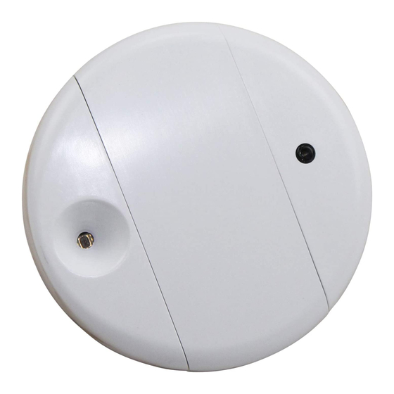
Dimensions . . . . . . . . . . . . . 2 . 4" diameter x 0.7" depth
DESCRIPTION
The Watt Stopper LS-101 is an interior photosensor that
a u to m a t i ca l ly turns a zone of lights ON and OFF based on
daylight levels. It is a low vo l tage dev i ce intended to
signal a power pack or relay panel.
The LS-101 is designed
to re q u i re minimal
a d j u stment at sta r t u p .
For more adva n ce d
a p p l i cations, an
o n b o a rd display and
t wo pushbuttons allow
for adjustments, if
needed. The display is
hidden under a re m ova b le
cove r. To ass i st with adjust m e n t ,
the LS-101 displays the current light
level re a d i n g .
Figure 2: Cover removed
The LS-101 is designed to be either ceiling- or wall-
m o u n ted. It has a wide range light sensor ca p a b le of
measuring from 1 to 1400 fo o tca n d le s .
SELECTING A LOCATION
The LS-101 co n t rols lights in areas that re ce i ve enough
daylight so that the electric lights can be re d u ced or
s w i tched OFF. It is important to select a lo cation for the
L S-101 where the daylight is re p re s e n ta t i ve of the
daylight throughout the co n t ro l led zone. Note the path of
s h a d ows. Daylighting co n t rol will be pro b lematic if part of
a co n t ro l led zone is in shadows while another part has
p lentiful daylight.
When the primary source of daylight is a window
(sidelighting), the LS-101 is typica l ly ceiling mounte d
within the daylit zone which ex tends 12 feet or le ss in
f rom the window. A good lo cation is often between the
w i n d ow and the first row of fix t u res. Figure 3 shows a
t y p i cal mounting lo cation for a sidelit applica t i o n .
Copyright© 2007 Watt Stopper/Legrand
by the co n t ro l led dev i ce .
(61mm x 17mm)
®
LS-101 Daylighting
Figure 1:
LS-101
Figure 3:
LS-101 Field of view, sidelight application
When the primary source of daylight is a skylight (to p l i g h t i n g ) ,
t h e re are seve ral options for mounting the LS-101. The
re commended mounting lo cations are shown in Figure 4.
I d e a l ly, the sensor is mounted on the South sidew a l l
looking North acro ss the light well.
It could also be mounted on the ceiling next to the
skylight, looking down at the flo o r.
A skylight may pro d u ce 5000 fo o tca n d les or more. If the
sensor is mounted so that it looks up into the skylight, the
daylight will exceed the maximum OFF setpoint of 1275fc
which is too low for this orientation.
Figure 4:
LS-101 Skylight application
LightSaver
C o n t ro l l e r
07076r2 4/2007
®
Advertisement
Table of Contents

Subscribe to Our Youtube Channel
Related Manuals for Watt Stopper LS-101


Summary of Contents for Watt Stopper LS-101
- Page 1 SELECTING A LOCATION daylight will exceed the maximum OFF setpoint of 1275fc The LS-101 co n t rols lights in areas that re ce i ve enough which is too low for this orientation. daylight so that the electric lights can be re d u ced or s w i tched OFF.
- Page 2 A d j u stment Menu SETUP submenu. It allows the occ u p a n c y light provided by the co n t ro l led fix t u re. signal to be co n n e c ted to the LS-101 at installation but late r be ignored without having to disconnect it.
- Page 3 The unit has 5 co lo r - coded wires. Connect to wires with the occupant may te m p o ra r i ly override the LS-101 signal to insulation ra ted for the application. Normally re commended wire turn lights ON even when light levels are high.
- Page 4 QUICK START TO ACTIVATING THE LS-101 FOR BASIC OPERATION C o m p le te all wiring and turn on the power to the LS-101, all acce ssories and lo a d s . 2 . Verify that the display shows LS101 #.# (the current software ve rs i o n ) .
- Page 5 OV R i n d i ca tor appears. The status indica tor LED also fa c i l i ta te easy te sting of the LS-101 light level settings. Afte r starts to flash slow ly. Pre ss Select again to turn the output ON 30 minutes, Te st Mode ends and the normal time delays are again while OV R i n d i ca tor remains lit.
- Page 6 L S - 1 0 1 ’s output has been fo rced ON or OFF by an ove r r i d e , f rom the optional wall switch, or the Control menu. If the blink is fa st (one blink every second) then the LS-101 is in te st mode.
Need help?
Do you have a question about the LS-101 and is the answer not in the manual?
Questions and answers