
Subscribe to Our Youtube Channel
Summary of Contents for Belden Grass Valley XVP-3901-DPI
- Page 1 XVP-3901-DPI 3G/HD/SD DPI INSERTER/EXTRACTOR WITH FRAME SYNC Guide to Installation and Operation M886-3800-101 2016-10-20...
- Page 2 Belden, Belden Sending All The Right Signals, and the Belden logo are trademarks or registered trademarks of Belden Inc. or its affiliated companies in the United States and other jurisdictions. Grass Valley, Miranda, UDC-3901, iControl, and Densité are trademarks or registered trademarks of Grass Valley Canada. Belden Inc., Grass Valley USA, LLC, and other parties may also have trademark rights in other terms used herein.
- Page 3 GUIDE TO INSTALLATION AND OPERATION Electromagnetic Compatibility This equipment has been tested for verification of compliance with FCC Part 15, Subpart B requirements for Class A digital devices. NOTE: This equipment has been tested and found to comply with the limits for a Class A digital device, pursuant to part 15 of the FCC Rules.
- Page 4 GUIDE TO INSTALLATION AND OPERATION XVP-3901-DPI...
-
Page 5: Table Of Contents
GUIDE TO INSTALLATION AND OPERATION Table of Contents XVP-3901-DPI 3G/HD/SD DPI Inserter/Extractor with Frame Sync ........1 Introduction ............................1 Features .............................. 1 Functional Block Diagram ........................2 Front Card-edge Interface ........................3 Installation ..........................4 Installation of Rear Connector Panels ....................4 Card Installation .......................... - Page 6 GUIDE TO INSTALLATION AND OPERATION 5.6.1 SCTE-104 Insert Tab ......................44 5.6.2 SCTE-104 Extract Tab ......................45 5.6.3 DPI Logging ......................... 46 5.6.4 Extra SCTE Operating Modes ..................... 46 Audio Processing panel ........................47 5.7.1 Audio Processing Tab ......................47 5.7.2 Downmix tab ........................
-
Page 7: Xvp-3901-Dpi 3G/Hd/Sd Dpi Inserter/Extractor With Frame Sync
1 XVP-3901-DPI 3G/HD/SD DPI Inserter/Extractor with Frame Sync 1.1 Introduction The XVP-3901-DPI from Grass Valley, a Belden Brand, is the perfect solution for digital program insertion (DPI) applications. It embeds SMPTE ST 2010 packets containing SCTE 104 DPI messages based on GPI triggers. It can also monitor embedded SMPTE ST 2010 packets for specific SCTE 104 split request messages and triggers the appropriate GPO. -
Page 8: Functional Block Diagram
GUIDE TO INSTALLATION AND OPERATION • Advanced video de-interlacing for higher image quality • User-programmable additional fixed video delay up to 15 frames • Automatic ARC using AFD (SMPTE ST-2016), video index (SMPTE RP-186) and WSS • Custom and fixed ARC presets •... -
Page 9: Front Card-Edge Interface
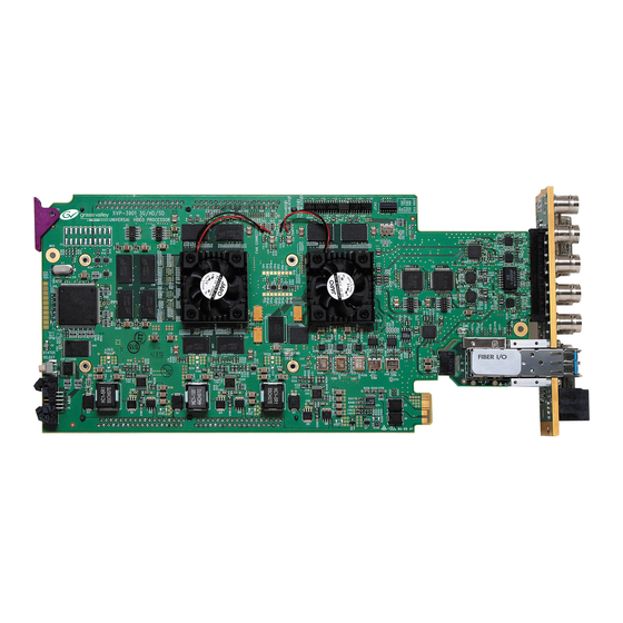
GUIDE TO INSTALLATION AND OPERATION This chart shows the video formats supported by the XVP-3901-DPI at its inputs and outputs XVP-3901-DPI Output Input 720p50 720p59.94 1080i50 1080i59.94 1080p50 1080p59.94 720p50 720p59.94 1080i50 1080i59.94 1080p23.98 1080pSF23.98 1080p25 1080p29.97 1080p50 1080p59.94 1.4 Front Card-edge Interface The front card-edge of the XVP-3901-DPI incorporates three elements: SDA-1101 - SD DIGITAL VIDEO DISTRIBUTION AMPLIFIER... -
Page 10: Installation
GUIDE TO INSTALLATION AND OPERATION 2 Installation 2.1 Installation of Rear Connector Panels The XVP-3901-DPI card is designed to fit into Grass Valley’s Densité-3 frame. Grass Valley Densité-series cards are each associated with a rear connector panel, which must be installed in the Densité... -
Page 11: Card Installation
GUIDE TO INSTALLATION AND OPERATION 3. Position the new panel and secure it in place with the captive screw(s) at the bottom. 2.2 Card Installation Once a matching rear connector panel has been installed, install the XVP-3901-DPI card as follows: 1. -
Page 12: Rear Panels And Connectors
GUIDE TO INSTALLATION AND OPERATION 2.5 Rear Panels and Connectors 2.5.1 Images of rear connector panels XVP-3901-75-3DRP-R XVP-3901-110-3DRP-R-F Figure 2.3 XVP-3901-DPI Rear Panels 2.5.2 Summary of rear panel connections The chart summarizes the connectors featured on each of the available XVP-3901-DPI rear panels. XVP-3901-75-3DRP-R XVP-3901-110-3DRP-R-F CONNECTORS... -
Page 13: Details Of Rear Panel Connections
GUIDE TO INSTALLATION AND OPERATION 2.5.3 Details of rear panel connections REF IN – Studio reference input For external synchronization, connect a black studio reference signal to the BNC labeled REF IN. The reference input must conform to SMPTE 170M/SMPTE 318M/ITU 624-4/BUT 470-6 for standard definition signals and SMPTE 274M / SMPTE 296M for high definition signals and is used to phase the HD/SD SDI outputs to the studio. - Page 14 GUIDE TO INSTALLATION AND OPERATION 3G/HD/SD SDI IN – Serial digital HD/SD input Connect up to two serial digital video signals, conforming to the SMPTE 424M standard for 3G input signals, SMPTE 292M standard for HD input signals or SMPTE 259M standard for SD input signals, to the BNC labeled HD/SD SDI IN.
- Page 15 GUIDE TO INSTALLATION AND OPERATION Fiber I/O – Fiber-optic inputs and outputs Rear panels whose part number ends in –F incorporate a fiber optic interface. The interface consists of two parts: • A socket on the rear panel into which an SFP interface module is plugged •...
-
Page 16: User Interface
GUIDE TO INSTALLATION AND OPERATION 3 User Interface 3.1 Control options The XVP-3901-DPI can be controlled in three different ways: • The local control panel and its push-buttons can be used to move through a menu of parameters and to adjust parameter values (see section 4). - Page 17 GUIDE TO INSTALLATION AND OPERATION LED Status Flashing Error Condition Green Yellow Reference mismatch Card System error Manual Freeze Test Mode AES 1 presence error AES 2 presence error AES 3 presence error ...
-
Page 18: Local Control Using The Densité Frame Control Panel
GUIDE TO INSTALLATION AND OPERATION 4 Local control using the Densité frame control panel There are two types of local control panel: Panel type Frame models Appearance Physical Densité-3, Densité-3+FR1 Open the frame door to access the panel. Touch screen Densité... -
Page 19: Remote Control Using Icontrol
GUIDE TO INSTALLATION AND OPERATION 5 Remote control using iControl The operation of the XVP-3901-DPI may be controlled using Grass Valley’s iControl system. • This manual describes the control panels associated with the XVP-3901-DPI and their use. • Please consult the iControl User’s Guide for information about setting up and operating iControl. In iControl Navigator or iControl Websites, double-click on the XVP-3901-DPI icon to open the control panel. - Page 20 GUIDE TO INSTALLATION AND OPERATION Move the mouse over an icon and a status message appears below the icon providing additional information. If there is an error, the error status message appears in the message area without mouse-over. • If there are multiple errors, the error messages cycle so all can be seen •...
- Page 21 GUIDE TO INSTALLATION AND OPERATION Icon #4 – Audio Status Audio OK (green) Yellow alarm condition detected on 1 or more channels (yellow) Red alarm condition detected on 1 or more channels (red) All audio disabled (gray) Card System Mismatch – the audio cards detected on the ABUS do not match the configuration selected in the ABUS panel (red) Icon #5 –...
-
Page 22: Video Input/Output Panel
GUIDE TO INSTALLATION AND OPERATION Icon #7 – Health Monitoring Hardware OK (green) Hardware Health Monitoring (Fan1, Fan2, Hardware fault detected) If this icon appears red, return the card to Grass Valley and specify the error code. (red) Section 2. The left portion of the window contains access buttons for all the parameter groups, which become highlighted when they are selected;... -
Page 23: Input/Output Config Tab
GUIDE TO INSTALLATION AND OPERATION 5.2.1 Input/Output Config Tab Input Config: use the pulldowns to select the rear panel input that will be used when the inputs are selected: • BNC IN – use one of the electrical inputs • Fiber IN –... -
Page 24: Deglitcher Tab
GUIDE TO INSTALLATION AND OPERATION • If input 2 and Failover mode are both selected, an error is reported by iControl and the card edge LED turns red. The second input is always required in this mode. • Both input signals must be present – the system cannot switch to input 2 if there is no signal there – and the absence of either of the signals will be flagged as an error (icon #2 and card-edge LED red) •... - Page 25 GUIDE TO INSTALLATION AND OPERATION H = 0 H=½ line H = 0 H=½ line H = 0 Line = x-1 Line = x Line = x+1 Ref signal clean switch region #1 clean switch region #2 clean switch region #3 Signal A Signal B Signal C...
-
Page 26: Freeze Tab
GUIDE TO INSTALLATION AND OPERATION Practical examples: Example 1: we have two SD (525) sources, one that indicates an offset of -25 µs with respect to the reference (A) and the other an offset of -35 µs (B). We know that a clean switch region limit is present at -½ line, which corresponds to -31.76 µs. -
Page 27: Sfp Info Tab
GUIDE TO INSTALLATION AND OPERATION Freeze Option Auto Freeze Mode Manual Mode • Freeze to last valid FIELD 1 Field 1 Freeze to last valid FIELD • Freeze to last valid FIELD 2 Field 2 • Freeze to last valid FRAME Frame •... -
Page 28: Video Processing Panel
GUIDE TO INSTALLATION AND OPERATION 5.3 Video Processing panel This panel contains color-correction parameters that apply to the input signal. You can configure the video processor differently for an SD input than for a 3G/HD input. The card will remember the different parameters and will load them automatically without user intervention based on whether the video input is SD or 3G/HD. -
Page 29: Advanced Tab
GUIDE TO INSTALLATION AND OPERATION 5.3.2 Advanced tab This tab provides individual controls for each of these parameters. Y Cb Cr mode RGB mode Slider name Range Slider name Range Y Gain -800 to +800 G Gain -800 to +800 Cb Gain -800 to +800 B Gain... -
Page 30: Video Outputs Panel - 3G/Hd Output Tab
GUIDE TO INSTALLATION AND OPERATION 5.4 Video Outputs panel – 3G/HD Output tab This panel allows control over several aspects of the video output: • aspect ratio conversion • timing control • image quality processing • metadata insertion. Note that since the XVP-3901-DPI does not include up/down/cross functionality, only limited functionality will be provided in this panel. -
Page 31: Hd Output - Arc Tab
GUIDE TO INSTALLATION AND OPERATION Note 1 – Auto mode: When Auto is selected, all the ARC values are automatically set based on the AFD flag detected at the input, and the ARC controls and presets described below are disabled. Annex 2 shows the AFD functions implemented. - Page 32 GUIDE TO INSTALLATION AND OPERATION Input: Tilt Once a smaller window has been established by cropping the input signal, it can be moved vertically (Tilt, expressed in lines) within the original image to place the desired portion of the image in view. By default, a Center check box beneath the Tilt scroll box forces the cropping window to be centered on the input window.
-
Page 33: Hd Output - Timing Tab
GUIDE TO INSTALLATION AND OPERATION Four scroll boxes with data windows for reporting and direct data entry are used to set the mask position on the four sides of the output image. Top and bottom position are set in lines, while left and right position are set in pixels. Masks should be adjusted by viewing the output on a video monitor and positioning the masks to cover edge effects with a minimum loss of clean picture content. -
Page 34: Hd Output - Meta Tab
GUIDE TO INSTALLATION AND OPERATION 5.4.3.1 Image Processing section MPEG Preprocessor Mode: This control changes the functionality of the detail enhancer. When MPEG preprocessor is activated (‘ON’), the adaptive detail enhancer will use a psycho-visual model to increase the level of details and the sharpness of edges without adding high frequency content that may be difficult to encode at a lower bit rate on a downstream MPEG encoder. - Page 35 GUIDE TO INSTALLATION AND OPERATION Insertion: Will always be in Auto mode which means that closed captioning information is processed as follows: • 3G/HD to 3G/HD Cross-conversion: EIA-708-B closed captions are detected at the input and re- inserted into the output 3G/HD signal conforming to the selected output 3H/HD format.
-
Page 36: Hd Output - Afd Tab
GUIDE TO INSTALLATION AND OPERATION Timecode binary group data is guaranteed to be transparent from input to output, except for 1080p23/1080p23sF/1080p25/1080p29 input formats. Presence: A presence icon is available for each type of incoming ATC packet. The Timecode 1 Presence icon turns green when VITC type timecode is detected and the Timecode 2 Presence icon turns green when LTC type timecode is detected. -
Page 37: Hd Output - De-Interlacer Tab
GUIDE TO INSTALLATION AND OPERATION • In AUTO mode, labeled DEFAULT and shows the current default AFD code to be used if no valid AFD code is detected at the input. • In FORCED mode, labeled FORCED, and shows the code that is forced into the system input regardless of the actual input code. -
Page 38: Video Outputs Panel - Sd Output Tab
GUIDE TO INSTALLATION AND OPERATION 5.5 Video Outputs panel – SD Output tab This panel allows control over several aspects of the standard definition video output: • aspect ratio conversion • timing control • image quality processing • metadata insertion. Note that since the XVP-3901-DPI does not include up/down/cross functionality, only limited functionality will be provided in this panel. -
Page 39: Sd Output - Arc Tab
GUIDE TO INSTALLATION AND OPERATION Note 1 – Auto mode: When Auto is selected, all the ARC values are automatically set based on the AFD flag detected at the input, and the ARC controls and presets described below are disabled. Annex 2 shows the AFD functions implemented. - Page 40 GUIDE TO INSTALLATION AND OPERATION 5.5.1.1 Input section Input: Crop – Horizontal and Vertical The crop controls allow selection of a portion of the original image – the amount of horizontal and vertical cropping is expressed as a percentage of the size of the original image. The user can manually adjust the level of horizontal and vertical cropping.
- Page 41 GUIDE TO INSTALLATION AND OPERATION 5.5.1.3 Presets section For convenience in manual operation, several of the most common conversion situations are pre-programmed into the XVP-3901-DPI, and can be quickly accessed. The available Presets change according to the AFD mode and Output Format selections made using the pulldowns on the input and output screens.
- Page 42 GUIDE TO INSTALLATION AND OPERATION Output Format 16:9 (when selected on the SD Video Output panel) Input Format (selected by AFD Mode pulldown) 16:9 Presets Output after ARC processing Table 5.1b Available Presets for various AFD Mode selections (16:9 output) 5.5.1.4 Masks section Mask: Horizontal and Vertical Sometimes with aspect ratio conversion, some of the edges of the original image are exposed in the output signal.
-
Page 43: Sd Output - Timing Tab
GUIDE TO INSTALLATION AND OPERATION be changed in the Advanced tab. The maximum amount of masking that can be introduced depends on the image format, and is measured starting from the edges of the displayed image, as shown in the following table. Masks can cover a maximum of 25% of the active area. -
Page 44: Sd Output - Advanced Tab
GUIDE TO INSTALLATION AND OPERATION 5.5.3 SD Output – Advanced tab The Advanced tab provides controls over the type and level of detail enhancement that will be performed, and the color of the mask. 5.5.3.1 Image Processing section Separate controls are provided for Horizontal and Vertical detail enhancement: Horz. -
Page 45: Sd Output - Meta Tab
GUIDE TO INSTALLATION AND OPERATION 5.5.3.3 HD to SD Output Resolution This is not a feature available in the XVP-3901-DPI as input will always be SD when output SD video. 5.5.4 SD Output – Meta tab The Meta tab provides resources to deal with Metadata incorporated into the incoming signal. It has three associated sub-tabs, described below. - Page 46 GUIDE TO INSTALLATION AND OPERATION • Dolby Metadata/AFD insertion will overwrite incoming TC/Teletext on insertion line. Refer to manual. [in blue letters] Conditions: SD to SD, both Dolby Metadata and AFD including VBI insertion enabled Consequences: Since Dolby metadata, AFD, and ancillary data like timecode cannot reside on the same line, any incoming timecode is blanked and Dolby metadata or AFD is inserted.
- Page 47 GUIDE TO INSTALLATION AND OPERATION • SD to SD: All incoming HANC packets within H blanking, VANC packets within VBI, and VBI lines may be bypassed to the output. 5.5.4.3 Meta / Namedropper sub-tab Namedropper is a method of inserting control information for down-stream graphics inserters.
-
Page 48: Sd Output - Afd Tab
GUIDE TO INSTALLATION AND OPERATION 5.5.5 SD Output – AFD tab The Active Format Descriptor (AFD) flag is used to identify the aspect ratio and protected areas of a video signal. The XVP- 3901-DPI uses this flag in some cases to adjust the output aspect ratio and image cropping to obtain the best possible presentation of the image. -
Page 49: Sd Output - De-Interlacer Tab
GUIDE TO INSTALLATION AND OPERATION The available types depend on the input format –AFD and VLI for SD-59.94 Hz inputs, and all three types for SD-50 Hz inputs. The set priority is used only during input AFD AUTO mode. The XVP-3901-DPI will examine the incoming data in the selected order of priority in order to extract the AFD data. -
Page 50: Scte-104 Panel
GUIDE TO INSTALLATION AND OPERATION 5.6 SCTE-104 panel The XVP-3901-DPI can be configured as an inserter or an extractor. You can use the Operating Mode parameter to specify the desired mode of operation. 5.6.1 SCTE-104 Insert Tab When the Operating Mode is configured as Insert, the card will insert SCTE messages in the video output. -
Page 51: Scte-104 Extract Tab
GUIDE TO INSTALLATION AND OPERATION 5.6.1.3 GPI The GPI are used to trigger the corresponding SCTE 104 events. For example, when the GPI 1 is triggered the corresponding SCTE-104 messages will be inserted. At the same time, the SCTE message is also sent to iControl for monitoring. -
Page 52: Dpi Logging
GUIDE TO INSTALLATION AND OPERATION 5.6.3 DPI Logging Regardless if the card is configured for “Insert” or “Extract”, all SCTE 104 events inserted or detected by the card will appear in the “Logging” window in human readable format. Refer to the picture on the right for an example log. When 2 GPIs are triggered at the same time, the 2 events will appear under the same timestamp. -
Page 53: Audio Processing Panel
GUIDE TO INSTALLATION AND OPERATION 5.7 Audio Processing panel The Audio Processing panel provides full audio processing and delay parameters for up to 32 channels. The first 16 channels come from the embedded input channels and/or the discrete AES inputs. The second set of 16 channels comes from the output channels of the Downmix module: The 32 processed audio channels can be assigned later to the 3G/HD output embedder, the SD output embedder, the... - Page 54 GUIDE TO INSTALLATION AND OPERATION Mute (speaker button): Mutes the selected audio channel Phase Invert: When checked, inverts the selected audio channel phase. Lock: “Locks” both channel sliders together for levels and delay (coarse only), so that moving one slider moves the other one as well.
-
Page 55: Downmix Tab
GUIDE TO INSTALLATION AND OPERATION 5.7.2 Downmix tab This tab provides resources to control the downmix of a “5.1 channel” surround-sound audio signal into an LtRt or LoRo stereo pair. The 5.1 terminology refers to six discrete audio channels, with the low frequency effect (LFE) channel of limited bandwidth designated as the “.1”... - Page 56 GUIDE TO INSTALLATION AND OPERATION Manual Downmix Config / Default Metadata Config The heading of this area of the panel changes depending on the selection in the Operating Mode pulldown above, but the available controls are the same in both cases. •...
-
Page 57: Aes Inputs Tab
GUIDE TO INSTALLATION AND OPERATION Follow Metadata Config: This section reports on Metadata presence in the selected path if the Follow Metadata Path 1 or 2 Operating Mode is selected. The four data boxes below the Metadata status icon indicate the current mode, plus the values in use for Dialnorm, Center Mix Level and Surround Mix Level. -
Page 58: Audio Outputs Panel
GUIDE TO INSTALLATION AND OPERATION video. This is equivalent to changing manually the audio delay in the audio processor. If you change the output timing of the card or the video output format, you may have to re-align the Dolby-E. •... -
Page 59: 1-2, Ch 3-4
GUIDE TO INSTALLATION AND OPERATION 5.8.1 CH 1-2, CH 3-4, … CH 15-16 tabs, and AES1, … AES4 tabs Each of these tabs provides all necessary controls for the output mixers. The example shown is for 3G/HD Output, CH 1-2, but all panels have the same controls. Operation Mode (Off, A, SUM(A+B), Mix): This menu allows the source(s) of each output channel to be selected –... -
Page 60: Config Tab
GUIDE TO INSTALLATION AND OPERATION 5.8.2 Config tab A Config tab is available in the 3G/HD tab and the SD tab, but not in the AES tab, In each case, the tab contains only an Output – Audio Insert pulldown. Use the pulldown in this tab to enable (AUTO) or disable (OFF) audio embedding in the output. - Page 61 GUIDE TO INSTALLATION AND OPERATION Zone Select the area of the image within which fingerprint data will be calculated and streamed. • The selected area is shown as a blue outline on the control panel window, superimposed over a thumbnail of the video.
-
Page 62: Reference Panel
GUIDE TO INSTALLATION AND OPERATION 5.10 Reference panel This group of parameters allows the selection of the reference to be used by the XVP-3901-DPI. Use the radio buttons in the Reference Source area to select from the following options: • Auto – this mode selects the first source detected in this order of priority: o External Reference input o URS... -
Page 63: Monitoring Panel
GUIDE TO INSTALLATION AND OPERATION 5.12 Monitoring panel 5.12.1 Thumbnails tab The thumbnail area displays thumbnail images for the inputs and outputs selected in the Player area. Player – Click the checkbox to display the thumbnail Control – Click the checkboxes to apply the Mode, Format, Quality and Refresh Rate settings to the these thumbnails. - Page 64 GUIDE TO INSTALLATION AND OPERATION 5.12.2.1 RALM Connections tab Use the radio buttons to turn the meter display ON (RALM) or OFF for the indicated channels. The meter appears directly above the controls. Reset Counter: click this button to reset the overload counter on the ALM display to zero. See the next section for instructions on setting up the overload counter.
-
Page 65: Test Panel
GUIDE TO INSTALLATION AND OPERATION 5.13 Test panel This panel contains a single checkbox that sends a 75% color bar test pattern (100% white), along with audio test tones (a continuous tone on right channel with pulsed tone on left channel in every pair) to the XVP-3901-DPI output. Figure 5-59 Test panel 5.14 Factory/Presets panel 5.14.1 Factory section... -
Page 66: Lock Input Selection Section
GUIDE TO INSTALLATION AND OPERATION Click Save to store the current parameter settings and values from the XVP-3901-DPI into the selected User Preset. The existing contents of the preset will be overwritten. 5.14.3 Lock Input Selection section When User Presets are saved, the input selection is saved as well. This means that changing User Preset may change input selection, depending on which one is associated with the User Preset. - Page 67 GUIDE TO INSTALLATION AND OPERATION The Profile column has a pulldown that allows you to select which profiles you will work with, and gives these choices: • Current, User1, User2, User3, User4, User5, All The Select column includes a checkbox (preselected checked) to confirm that you want to work with the current card. 5.14.5.2 Save Profile to Disk…...
-
Page 68: Options Panel
GUIDE TO INSTALLATION AND OPERATION The Select column includes a checkbox to identify which XVP-3901-DPI cards you wish to copy profiles into from the current card. • For convenience, a Select all checkbox is provided in the column header Click Copy to copy the selected profiles from this card into the selected other XVP-3901-DPI cards •... -
Page 69: Key/Fill Option
GUIDE TO INSTALLATION AND OPERATION 5.15.2 Key/Fill option: This option is used to enable the background key/fill functionality for the side panels and letterbox. Figure 5-65 Key/Fill option 5.16 Alarm Config panel This panel allows the alarm reporting of the XVP-3901-DPI to be configured. The panel opens in a new window when the button is clicked, and can be resized if needed. - Page 70 GUIDE TO INSTALLATION AND OPERATION The Card LED, Overall alarm and GSM contribution columns contain pulldown lists that allow the level of contribution of each individual alarm to the alarm named in the column heading to be set. Click on the alarm icon to see the available levels;...
- Page 71 GUIDE TO INSTALLATION AND OPERATION Levels associated with these alarms: The pulldown lists may contain some or all of the following options: The alarm makes no contribution (black icon) The alarm is of minor importance (yellow icon) The alarm is of major importance (orange icon) The alarm is of critical importance (red icon) The alarm exists but has no effect (used for text and composite alarms) Shortcut: if you click in one of the Set All boxes beside a section heading, you will open a pulldown that lets you...
-
Page 72: Info Panel
GUIDE TO INSTALLATION AND OPERATION Get alarm keys Click this button to open a save dialog where you can save a file containing a list of all alarms on this card and their current values, along with an Alarm Key for each. The alarm keys are useful for system integration and troubleshooting. - Page 73 GUIDE TO INSTALLATION AND OPERATION Three buttons in the panel give access to other information. • Details…: Reports the Firmware version, service version, and panel version for this card Figure 5-71 Details window • Advanced…: Shows the LongID for this card. The LongID is the address of this XVP-3901-DPI in the iControl network.
-
Page 74: Specifications
720p59.94, 720p50 SMPTE ST 425-1:2014 Level A (mapping 1), Level B: 1080p59.94, 1080p50 CABLE LENGTH * 300 m Belden 1694A at 270 Mbps 150 m Belden 1694A at 1.485 Gbps 120 m Belden 1694A at 2.970 Gbps RETURN LOSS * >15 dB up to 3 GHz... - Page 75 GUIDE TO INSTALLATION AND OPERATION AUDIO OUTPUT (4) SAMPLING FREQUENCY 48 KHz QUANTIZATION 24 bits AES3 • LEVEL 2.75 Vp-p • INPUT IMPEDANCE 110 ohms balanced AES3-id • LEVEL 1.0 Vp-p • INPUT IMPEDANCE 75 ohms • RETURN LOSS 15 dB @ 6 MHz AUDIO PROCESSING PERFORMANCE QUANTIZATION 24 bits...
- Page 76 GUIDE TO INSTALLATION AND OPERATION TEST PATTERN GENERATOR VIDEO Color bars: 100% white bar with 75% color AUDIO Left channel: pulsed 1 KHz tone Right channel: steady 1 KHz tone MISCELLANEOUS POWER 25 W 70 | XVP-3901-DPI...
-
Page 77: Contact Us
GUIDE TO INSTALLATION AND OPERATION 7 Contact Us Grass Valley Technical Support For technical assistance, contact our international support center, at 1-800-547-8949 (US and Canada) or +1 530 478 4148. To obtain a local phone number for the support center nearest you, please consult the Contact Us section of Grass Valley’s website (www.grassvalley.com). -
Page 78: Annex 1 - Xvp-3901 Local User Interface
GUIDE TO INSTALLATION AND OPERATION ANNEX 1 – XVP-3901 Local User Interface 72 | XVP-3901-DPI... - Page 79 GUIDE TO INSTALLATION AND OPERATION XVP-3901-DPI | 73...
- Page 80 GUIDE TO INSTALLATION AND OPERATION 74 | XVP-3901-DPI...
- Page 81 GUIDE TO INSTALLATION AND OPERATION XVP-3901-DPI | 75...
-
Page 82: Annex 2 - Afd Functions
GUIDE TO INSTALLATION AND OPERATION ANNEX 2 – AFD FUNCTIONS The charts below show the conversions that will be performed by the XVP-3901 when the Active Format Descriptor (AFD) processing is activated by selecting AUTO in the AFD Mode pulldown on the input screen of the HD Video Output or SD Video Output panels. - Page 83 GUIDE TO INSTALLATION AND OPERATION Input signal Output signal 16:9 4:3 Full frame image in a 4:3 frame 4:3 Full frame image in a 4:3 frame 4:3 Pillar-box image in 16:9 frame (16:9_9) (4:3_8) (4:3_8)* 4:3 Full frame image in a 4:3 frame 4:3 Full frame image in a 4:3 frame 4:3 Pillar-box image in 16:9 frame (use preferred 4:3_8 code instead)
- Page 84 GUIDE TO INSTALLATION AND OPERATION Input signal Output signal 16:9 16:9 Full frame image in a 16:9 frame 16:9 Letterbox image in 4:3 frame 16:9 Full frame image in a 16:9 frame (use preferred 16:9_8 flag instead) (16:9_2) (4:3_10) (16:9_2)* 14:9 Pillar-box image in a 16:9 frame 14:9 Letterbox image in a 4:3 frame 14:9 Pillar-box image in a 16:9 frame...
- Page 85 GUIDE TO INSTALLATION AND OPERATION Input signal Output signal 16:9 4:3 Pillar-box image Shoot and protect 4:3 Image shoot and protect 14:9 in a 14:9 Pillar-box image in a 16:9 frame 14:9 in a 16:9 frame 4:3 frame (16:9_13) (4:3_13)* (16:9_11) 16:9 Image shoot and protect 14:9 in a 14:9 Letterbox image in a 4:3 frame...
-
Page 86: Annex 3 - Installing The Optical Interface
GUIDE TO INSTALLATION AND OPERATION ANNEX 3 – Installing the Optical Interface Installing and removing the Fiber I/O interface cartridge requires special care. This annex describes the process. rear panel incorporates a fiber optic interface. The interface consists of two parts: XVP-3901-110-3DRP-R-F •... - Page 87 GUIDE TO INSTALLATION AND OPERATION 3. Slide the module straight into the socket, and push gently until it clicks into position. Connecting the fiber optic cables 1. Remove the dust plug from the SFP module if present 2. Verify that the exposed end of the optical fiber in the LC connector is clean •...
Need help?
Do you have a question about the Grass Valley XVP-3901-DPI and is the answer not in the manual?
Questions and answers