
Subscribe to Our Youtube Channel
Related Manuals for Juniper TCX1000-RDM20


Summary of Contents for Juniper TCX1000-RDM20
- Page 1 TCX1000 Programmable ROADM Hardware Guide Modified: 2019-01-09 Copyright © 2019, Juniper Networks, Inc.
- Page 2 END USER LICENSE AGREEMENT The Juniper Networks product that is the subject of this technical documentation consists of (or is intended for use with) Juniper Networks software. Use of such software is subject to the terms and conditions of the End User License Agreement (“EULA”) posted at https://support.juniper.net/support/eula/.
-
Page 3: Table Of Contents
TCX1000-RDM20 Components and Descriptions ..... . 9 TCX1000-RDM20 Chassis Description ........9 TCX1000-RDM20 Front Panel and FRU Panel . - Page 4 Before You Begin Mounting the TCX1000-RDM20 ..... 63 Mounting the TCX1000-RDM20 ........64 Chapter 12 Connecting the TCX1000-RDM20 to Ground .
- Page 5 Providing Power to the TCX1000-RDM20 ......73 Connecting AC Power to a TCX1000-RDM20 ......73 Connecting DC Power to a TCX1000-RDM20 .
- Page 6 Powering Off a TCX1000-RDM20 ........
- Page 7 Agency Approvals and Compliance Statements ..... 189 TCX1000-RDM20 Agency Approvals ........189 Compliance Statements for EMC Requirements .
- Page 8 TCX1000 Programmable ROADM Hardware Guide viii Copyright © 2019, Juniper Networks, Inc.
-
Page 9: About The Documentation
® To obtain the most current version of all Juniper Networks technical documentation, see the product documentation page on the Juniper Networks website at https://www.juniper.net/documentation/ If the information in the latest release notes differs from the information in the documentation, follow the product Release Notes. - Page 10 RFC 1997, BGP Communities Attribute Italic text like this Represents variables (options for which Configure the machine’s domain name: you substitute a value) in commands or [edit] configuration statements. root@# set system domain-name domain-name Copyright © 2019, Juniper Networks, Inc.
-
Page 11: Documentation Feedback
We encourage you to provide feedback so that we can improve our documentation. You can use either of the following methods: Online feedback system—Click TechLibrary Feedback, on the lower right of any page on the Juniper Networks TechLibrary site, and do one of the following: Copyright © 2019, Juniper Networks, Inc. -
Page 12: Requesting Technical Support
7 days a week, 365 days a year. Self-Help Online Tools and Resources For quick and easy problem resolution, Juniper Networks has designed an online self-service portal called the Customer Support Center (CSC) that provides you with the following features: Find CSC offerings: https://www.juniper.net/customers/support/... -
Page 13: Creating A Service Request With Jtac
About the Documentation Join and participate in the Juniper Networks Community Forum: https://www.juniper.net/company/communities/ Create a service request online: https://myjuniper.juniper.net To verify service entitlement by product serial number, use our Serial Number Entitlement (SNE) Tool: https://entitlementsearch.juniper.net/entitlementsearch/ Creating a Service Request with JTAC You can create a service request with JTAC on the Web or by telephone. - Page 14 TCX1000 Programmable ROADM Hardware Guide Copyright © 2019, Juniper Networks, Inc.
-
Page 15: Overview
PART 1 Overview System Overview on page 3 TCX1000-RDM20 Components and Descriptions on page 9 Cooling System Components and Descriptions on page 17 Power System Components and Descriptions on page 21 Copyright © 2019, Juniper Networks, Inc. - Page 16 TCX1000 Programmable ROADM Hardware Guide Copyright © 2019, Juniper Networks, Inc.
-
Page 17: System Overview
TCX1000-RDM20 Hardware Component Overview on page 5 TCX1000-RDM20 Component Redundancy on page 6 TCX1000-RDM20 Description The Juniper Networks TCX1000-RDM20 is a standalone 20-port programmable optical add/drop multiplexer (ROADM) with removable AC or DC power supplies and cooling fans. The TCX1000-RDM20 provides:... -
Page 18: Front Panel
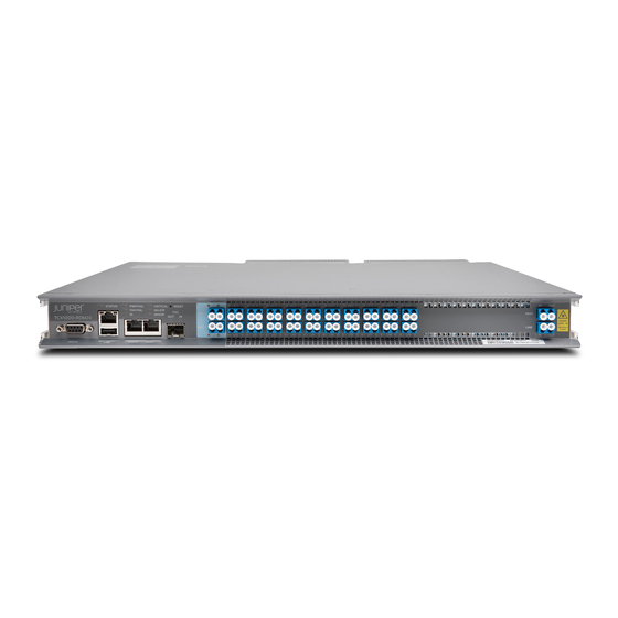
Front Panel on page 4 FRU Panel on page 4 Front Panel The front panel of the TCX1000-RDM20 contains a serial port, USB port, Ethernet ports, small form-factor pluggable (SFP) port, status LEDS, 20 universal ports, LINE IN ports, monitor ports, and system status LEDs. -
Page 19: Tcx1000-Rdm20 Hardware Component Overview
Power supplies 2—Grounding point The cooling system in a TCX1000-RDM20 consists of two fan modules. These fan modules can be hot-swapped—you do not need to power off the TCX1000-RDM20 or disrupt the functioning of the TCX1000-RDM20 to replace a fan module. The TCX1000-RDM20 has two 650-W power supplies, either AC or DC depending on your configuration. -
Page 20: Tcx1000-Rdm20 Component Redundancy
The following hardware components provide redundancy on the TCX1000-RDM20 models: Cooling system—The TCX1000-RDM20 has two fan modules . Each module is a redundant unit containing three individual fans. If a fan module fails and the other fan module is unable to keep the TCX1000-RDM20 within the desired temperature thresholds, and the power supply module alarm is at 75°... - Page 21 Related TCX1000-RDM20 Cooling System Description on page 17 Documentation TCX1000-RDM20 AC Power Supply Description on page 21 TCX1000-RDM20 DC Power Supply Description on page 22 Copyright © 2019, Juniper Networks, Inc.
- Page 22 TCX1000 Programmable ROADM Hardware Guide Copyright © 2019, Juniper Networks, Inc.
-
Page 23: Tcx1000-Rdm20 Components And Descriptions
TCX1000-RDM20 Management Port LEDs on page 15 TCX1000-RDM20 Chassis Description The TCX1000-RDM20 chassis is a rigid sheet metal structure that houses all the other hardware components. The chassis measures 1.70 in. (4.31 cm) high, 23 in. (58.42 cm) deep, and 17.6 in. (44.70 cm) wide (without the mounting brackets and FRUs). The chassis can be installed in racks or cabinets. - Page 24 Longer than 10 seconds Cold reset of the TCX1000-RDM20. It shuts down all traffic passing through the device. This forces a restart even in the event system software has become unresponsive. This also resets all active optical modules within the device.
-
Page 25: Fru Panel
2—Grounding pole The cooling system in TCX1000-RDM20 consists of two fan modules. The fan modules can be hot-swapped—you do not need to power off the TCX1000-RDM20 or disrupt the TCX1000-RDM20 function to replace a fan module. The TCX1000-RDM20 has two 650-W power supplies, either AC or DC depending on your configuration. -
Page 26: Tcx1000-Rdm20 Chassis And Port Status Leds
TCX1000 Programmable ROADM Hardware Guide TCX1000-RDM20 Chassis and Port Status LEDs The TCX1000-RDM20 has seven status LEDs on the front panel of the chassis (see Figure 5 on page 12)—a system status LED ( ), a power failure LED (... - Page 27 One of the fan modules has failed. ID ( ) LED Unlit Not available. Table 8 on page 13 describes the port status LEDs on the TCX1000-RDM20. Table 8: TCX1000-RDM20 Port Status LEDs Name Color State Description SFP out port status...
-
Page 28: Tcx1000-Rdm20 Management Panel
Booster on, automatic power reduction (APR) active. Related TCX1000-RDM20 Management Panel on page 14 Documentation TCX1000-RDM20 Management Panel The TCX1000-RDM20 management panel is found on the front panel (see Figure 6 on page 14). Figure 6: TCX1000-RDM20 Management Panel Components 1— SERIAL 4—... -
Page 29: Tcx1000-Rdm20 Management Port Leds
Chapter 2: TCX1000-RDM20 Components and Descriptions Related TCX1000-RDM20 Management Port LEDs on page 15 Documentation TCX1000-RDM20 Chassis and Port Status LEDs on page 12 TCX1000-RDM20 Management Port LEDs The management port—labeled —on the TCX1000-RDM20 is located on the ETH CRAFT management panel. - Page 30 TCX1000 Programmable ROADM Hardware Guide Copyright © 2019, Juniper Networks, Inc.
-
Page 31: Cooling System Components And Descriptions
TCX1000-RDM20 Cooling System Description on page 17 TCX1000-RDM20 Cooling System Description The cooling system in a TCX1000-RDM20 consists of two fan modules installed in the field-replaceable unit (FRU) panel and each power supply has a dual rotor counter-rotating fan in them. -
Page 32: Airflow Through The Chassis
NOTE: Both fan modules must be installed for optimal operation of the TCX1000-RDM20, if there is only one fan than there will be no redundancy. Each TCX1000-RDM20 has a fan LED located to the left of the fan. Figure 10 on page 18 shows the location of the LEDs on a TCX1000-RDM20. - Page 33 Chapter 3: Cooling System Components and Descriptions Figure 11: Chassis Airflow Related Removing a Fan Module from a TCX1000-RDM20 on page 117 Documentation Installing a Fan Module in a TCX1000-RDM20 on page 118 Prevention of Electrostatic Discharge Damage on page 178...
- Page 34 TCX1000 Programmable ROADM Hardware Guide Copyright © 2019, Juniper Networks, Inc.
-
Page 35: Power System Components And Descriptions
21) are hot-removable and hot-insertable field-replaceable units (FRUs) that you can install without powering off the TCX1000-RDM20 or disrupting the functioning of the TCX1000-RDM20. The TCX1000-RDM20 has two power supplies. Both power supplies are initially installed at the factory. See... -
Page 36: Tcx1000-Rdm20 Dc Power Supply Description
Each of the 650-W power supplies has a single AC input. The power supply provides 12-VDC output with a standby voltage of 12 VDC. A TCX1000-RDM20 has twice the number of power supplies needed to power all of the components in the device, which is known as 1+1 redundancy. - Page 37 Each of the two 650-W power supplies has a single DC input. The power supply provides 12 VDC output with a standby voltage of 12 VDC. A TCX1000-RDM20 has twice the number of power supplies needed to power all of the components in the device, which is known as 1+1 redundancy.
-
Page 38: Tcx1000-Rdm20 Power Supply Leds
TCX1000-RDM20 Power Supply LEDs on page 24 Documentation TCX1000-RDM20 DC Power Specifications on page 53 Connecting DC Power to a TCX1000-RDM20 on page 75 TCX1000-RDM20 Field-Replaceable Units on page 115 Prevention of Electrostatic Discharge Damage on page 178 TCX1000-RDM20 Power Supply LEDs... - Page 39 There is an internal failure. Blinking There is an internal warning. Related TCX1000-RDM20 AC Power Supply Description on page 21 Documentation TCX1000-RDM20 DC Power Supply Description on page 22 TCX1000-RDM20 AC Power Cord Specifications on page 51 TCX1000-RDM20 DC Power Specifications on page 53...
- Page 40 TCX1000 Programmable ROADM Hardware Guide Copyright © 2019, Juniper Networks, Inc.
- Page 41 Preparation Overview on page 29 Power Consumption Specifications on page 49 AC Power Specifications and Requirements on page 51 DC Power Specifications and Requirements on page 53 Management Cable Specifications and Pinouts on page 55 Copyright © 2019, Juniper Networks, Inc.
- Page 42 TCX1000 Programmable ROADM Hardware Guide Copyright © 2019, Juniper Networks, Inc.
-
Page 43: Preparation Overview
TCX1000-RDM20 Optical Specifications on page 35 TCX1000-2D8CMD Optical Specifications on page 36 TCX1000-RDM20 SFP Kit Optical Specifications on page 37 TCX1000-RDM20 Channel Center Wavelength and Frequency Specifications on page 38 96-Channel Fixed Mux/Demux (FMD96) DWDM 50-GHz Wavelength Specifications on page 42... -
Page 44: Tcx1000-Rdm20 Rack Requirements
Overview of Installing the TCX1000-RDM20 on page 59 Mounting a TCX1000-RDM20 in a Rack or Cabinet on page 62 TCX1000-RDM20 Rack Requirements The TCX1000-RDM20 chassis is designed to be installed in two-post or four-post racks. Rack requirements consist of: Rack type Mounting bracket hole spacing Copyright ©... -
Page 45: Tcx1000-Rdm20 Cabinet Requirements
(document number EIA-310–D) published by the Electronics Components Industry Association http://www.ecianow.org/ Mounting bracket hole The holes in the mounting brackets are spaced at 1.25 in. (or 3.17 cm), so that the TCX1000-RDM20 spacing can be mounted in any rack that provides holes spaced at that distance. -
Page 46: Tcx1000-Rdm20 Physical Specifications
If the cabinet contains a top or doors, perforations in these elements assist with removing the hot air exhaust. Install the TCX1000-RDM20 in the cabinet in a way that maximizes the open space on the field-replaceable unit (FRU) side of the chassis. This maximizes the clearance for critical airflow. -
Page 47: Maintenance
TCX1000-RDM20 Rack Requirements on page 30 Documentation TCX1000-RDM20 Cabinet Requirements on page 31 Mounting a TCX1000-RDM20 in a Rack or Cabinet on page 62 Connecting the TCX1000-RDM20 Grounding Cable on page 70 TCX1000-RDM20 Clearance Requirements for Airflow and Hardware Maintenance... -
Page 48: Tcx1000-Rdm20 Environmental Requirements And Specifications
TCX1000 Programmable ROADM Hardware Guide TCX1000-RDM20 Cabinet Requirements on page 31 TCX1000-RDM20 Environmental Requirements and Specifications The TCX1000-RDM20 must be installed in a rack or cabinet. It must be housed in a dry, clean, well-ventilated, and temperature-controlled environment. Follow these environmental guidelines: The site must be as dust-free as possible, because dust can clog air intake vents and filters, reducing the efficiency of the TCX1000-RDM20 cooling system. -
Page 49: Tcx1000-2D8Cmd Environmental Requirements And Specifications
Chapter 5: Preparation Overview Related TCX1000-RDM20 Clearance Requirements for Airflow and Hardware Maintenance on Documentation page 33 Overview of Installing the TCX1000-RDM20 on page 59 TCX1000-2D8CMD Environmental Requirements and Specifications The TCX1000-2D8CMD must be installed in a rack. It must be housed in a dry, clean, well-ventilated, and temperature-controlled environment. -
Page 50: Tcx1000-2D8Cmd Optical Specifications
TCX1000 Programmable ROADM Hardware Guide Table 18: Optical Specifications for the TCX1000-RDM20 (continued) Parameter Minimum Maximum Unit Description Per channel input power at universal ports (50 GHz channel –10.7 Ports U0 to U19 Per channel output power at universal ports (50 GHz channel –3.5... -
Page 51: Tcx1000-Rdm20 Sfp Kit Optical Specifications
Related Mounting and Installing the TCX1000-2D8CMD in a Rack on page 107 Documentation Connecting the TCX1000-2D8CMD to a TCX1000-RDM20 on page 110 TCX1000-RDM20 SFP Kit Optical Specifications Table 20 on page 37 lists the optical specifications for the items in the SFP kit for the TCX1000-RDM20. -
Page 52: Specifications
TCX1000 Programmable ROADM Hardware Guide Table 20: SFP Kit Optical Specifications for the TCX1000-RDM20 (continued) Part Parameter Minimum Type Maximum Units Fixed optical Connector type – LC/UPC – – attenuators Insertion loss, – – C-band Patch cord Connector type –... - Page 53 Chapter 5: Preparation Overview Table 21: Channel Center Wavelength and Frequency for the TCX1000-RDM20 (continued) Channel Center Wavelength (nm) Channel Center Frequency (THz) Channel Spacing 1533.86 195.45 50 GHz 1534.25 195.40 50 GHz 1534.64 195.35 50 GHz 1535.04 195.30 50 GHz 1535.43...
- Page 54 TCX1000 Programmable ROADM Hardware Guide Table 21: Channel Center Wavelength and Frequency for the TCX1000-RDM20 (continued) Channel Center Wavelength (nm) Channel Center Frequency (THz) Channel Spacing 1543.33 194.25 50 GHz 1543.73 194.20 50 GHz 1544.13 194.15 50 GHz 1544.53 194.10 50 GHz 1544.92...
- Page 55 Chapter 5: Preparation Overview Table 21: Channel Center Wavelength and Frequency for the TCX1000-RDM20 (continued) Channel Center Wavelength (nm) Channel Center Frequency (THz) Channel Spacing 1552.93 193.05 50 GHz 1553.33 50 GHz 1553.73 192.95 50 GHz 1554.13 192.9 50 GHz 1554.54...
-
Page 56: 96-Channel Fixed Mux/Demux (Fmd96) Dwdm 50-Ghz Wavelength
TCX1000 Programmable ROADM Hardware Guide Table 21: Channel Center Wavelength and Frequency for the TCX1000-RDM20 (continued) Channel Center Wavelength (nm) Channel Center Frequency (THz) Channel Spacing 1562.64 191.85 50 GHz 1563.05 191.80 50 GHz 1563.45 191.75 50 GHz 1563.86 191.70 50 GHz 1564.27... - Page 57 195.50 1533.47 195.45 1533.86 195.40 1534.25 195.35 1534.64 195.30 1535.04 195.25 1535.43 195.20 1535.82 195.15 1536.22 195.10 1536.61 195.05 1537.00 195.00 1537.40 194.95 1537.79 194.90 1538.19 194.85 1538.58 194.80 1538.98 194.75 1539.37 194.70 1539.77 Copyright © 2019, Juniper Networks, Inc.
- Page 58 194.35 1542.54 194.30 1542.94 194.25 1543.33 194.20 1543.73 194.15 1544.13 194.10 1544.53 194.05 1544.92 194.00 1545.32 193.95 1545.72 193.90 1546.12 193.85 1546.52 193.80 1546.92 193.75 1547.32 193.70 1547.72 193.65 1548.11 193.60 1548.51 193.55 1548.91 Copyright © 2019, Juniper Networks, Inc.
- Page 59 193.20 1551.72 193.15 1552.12 193.10 1552.52 193.05 1552.93 193.00 1553.33 192.95 1553.73 192.90 1554.13 192.85 1554.54 192.80 1554.94 192.75 1555.34 192.70 1555.75 192.65 1556.15 192.60 1556.55 192.55 1556.96 192.50 1557.36 192.45 1557.77 192.40 1558.17 Copyright © 2019, Juniper Networks, Inc.
- Page 60 192.15 1560.20 192.10 1560.61 192.05 1561.01 192.00 1561.42 191.95 1561.83 191.90 1562.23 191.85 1562.64 191.80 1563.05 191.75 1563.45 191.70 1563.86 191.65 1564.27 191.60 1564.68 191.55 1565.09 191.50 1565.50 191.45 1565.91 191.40 1566.31 191.35 1566.72 Copyright © 2019, Juniper Networks, Inc.
-
Page 61: Tcx1000-Rdm20 Chassis Grounding Cable And Lug Specifications
Before connecting the TCX1000-RDM20 to earth ground, review the following information: A protective earthing terminal bracket is required for connecting the TCX1000-RDM20 to earth ground. This bracket is attached to the rear of the TCX1000-RDM20 chassis and provides a protective earthing terminal for the device. The grounding points require two #10-32 UNF screws. - Page 62 TCX1000 Programmable ROADM Hardware Guide Copyright © 2019, Juniper Networks, Inc.
-
Page 63: Power Consumption Specifications
CHAPTER 6 Power Consumption Specifications TCX1000-RDM20 Power Consumption Specifications on page 49 TCX1000-RDM20 Power Consumption Specifications Table 23 on page 49 describes the power consumption specifications for the TCX1000-RDM20. Table 23: TCX1000-RDM20 Power Consumptions Specifications Item Minimum Typical Maximum TCX1000-RDM20-AC –... - Page 64 TCX1000 Programmable ROADM Hardware Guide Copyright © 2019, Juniper Networks, Inc.
-
Page 65: Ac Power Specifications And Requirements
CHAPTER 7 AC Power Specifications and Requirements TCX1000-RDM20 AC Power Specifications on page 51 TCX1000-RDM20 AC Power Cord Specifications on page 51 TCX1000-RDM20 AC Power Specifications Table 25 on page 51 describes the AC power specifications for a TCX1000-RDM20. Table 25: AC Power Specifications for the TCX1000-RDM20... - Page 66 Code (CEC) Section 4-010(3). The cords that can be ordered for the TCX1000-RDM20 are in compliance. Table 26 on page 52 lists AC power cord specifications provided for each country or region. Table 26: AC Power Cord Specifications for the TCX1000-RDM20 Country Model Number Electrical Specification Plug Type...
-
Page 67: Dc Power Specifications And Requirements
CHAPTER 8 DC Power Specifications and Requirements TCX1000-RDM20 DC Power Specifications on page 53 TCX1000-RDM20 DC Power Cable and Lugs Specifications on page 53 TCX1000-RDM20 DC Power Specifications Table 27 on page 53 describes the DC power specifications for a TCX1000-RDM20. -
Page 68: Dc Power Cables
TCX1000-RDM20 DC Power Supply Description on page 22 Documentation Connecting DC Power to a TCX1000-RDM20 on page 75 Removing a Power Supply from a TCX1000-RDM20 on page 121 TCX1000-RDM20 DC Power Electrical Safety Guidelines on page 180 Copyright © 2019, Juniper Networks, Inc. -
Page 69: Management Cable Specifications And Pinouts
TCX1000-RDM20 Table 29 on page 55 lists the specifications for the cables that connect the TCX1000-RDM20 to a management device. Table 29: Cable Specifications for Console and Management Connections for the TCX1000-RDM20 Device Port on TCX1000-RDM20 Cable Specification Maximum Length... - Page 70 If your laptop or PC does not have a DB-9 male connector pin and you want to connect your laptop or PC directly to a TCX1000-RDM20, use a combination of the RJ-45 cable and RJ-45 to DB-9 adapter and a USB to DB-9 male adapter.
-
Page 71: Initial Installation And Configuration
Connecting the TCX1000-RDM20 to Ground on page 69 Providing Power to the TCX1000-RDM20 on page 73 Connecting the TCX1000-RDM20 to External Devices on page 79 Performing Initial Configuration on page 85 Installing and Connecting the FMD96 Modules on page 93 Installing and Connecting the TCX1000-2D8CMD Modules on page 105 Copyright ©... - Page 72 TCX1000 Programmable ROADM Hardware Guide Copyright © 2019, Juniper Networks, Inc.
-
Page 73: Installation Overview
Connecting the TCX1000-RDM20 to the Network and External Devices on page 81 Set the IP address by following the instructions in: Making a Craft Ethernet port CLI Connection for the TCX1000-RDM20 on page 85 Performing the Initial Configuration for the TCX1000-RDM20 on page 86... - Page 74 TCX1000 Programmable ROADM Hardware Guide Copyright © 2019, Juniper Networks, Inc.
-
Page 75: Unpacking And Mounting The Tcx1000-Rdm20
Mounting a TCX1000-RDM20 in a Rack or Cabinet on page 62 Unpacking the TCX1000-RDM20 The TCX1000-RDM20 chassis is a rigid sheet-metal structure that houses the hardware components. The TCX1000-RDM20 is shipped in a cardboard carton, secured with foam packing material. The carton also contains an accessory kit and quick start instructions. -
Page 76: Mounting A Tcx1000-Rdm20 In A Rack Or Cabinet
Mounting a TCX1000-RDM20 in a Rack or Cabinet on page 62 Mounting a TCX1000-RDM20 in a Rack or Cabinet You can mount a TCX1000-RDM20 in a two-post or four-post rack by using the attached mounting brackets. Before You Begin Mounting the TCX1000-RDM20 on page 63 Mounting the TCX1000-RDM20 on page 64 Copyright ©... -
Page 77: Before You Begin Mounting The Tcx1000-Rdm20
Chapter 11: Unpacking and Mounting the TCX1000-RDM20 Before You Begin Mounting the TCX1000-RDM20 Before you begin mounting a TCX1000-RDM20 in the rack: Ensure that you understand how to prevent electrostatic discharge (ESD) damage. “Prevention of Electrostatic Discharge Damage” on page 178. -
Page 78: Mounting The Tcx1000-Rdm20
21-in. or 23-in. brackets by using the same screws. NOTE: This procedure requires two persons. Do not attempt to do it alone. To mount the TCX1000-RDM20 on four posts in a rack using the 19-in. mounting brackets, follow these steps: Copyright © 2019, Juniper Networks, Inc. - Page 79 Unscrew the 19-in. rear brackets from the chassis and set them aside, saving the screws. Position the TCX1000-RDM20 so the FRUs are next to the hot aisle. Have one person grasp both sides of the chassis, lift it, and position it in the rack so that the front bracket is aligned with the rack holes.
- Page 80 Figure 20 on page Figure 20: Installing the Fiber Management Clip on the TCX1000-RDM20 To mount the TCX1000-RDM20 on two posts in a rack using the 19-in. mounting brackets, follow these steps: Attach the ESD grounding strap to your bare wrist and to a site ESD point.
- Page 81 Figure 22 on page Figure 22: Installing the Fiber Management Clip on the TCX1000-RDM20 Related Mounting a TCX1000-RDM20 in a Rack or Cabinet on page 62 Documentation Connecting the TCX1000-RDM20 Grounding Cable on page 70 Connecting AC Power to a TCX1000-RDM20 on page 73...
- Page 82 TCX1000 Programmable ROADM Hardware Guide Connecting DC Power to a TCX1000-RDM20 on page 75 Copyright © 2019, Juniper Networks, Inc.
-
Page 83: Connecting The Tcx1000-Rdm20 To Ground
CHAPTER 12 Connecting the TCX1000-RDM20 to Ground Connecting the TCX1000-RDM20 Grounding Cable on page 70 Copyright © 2019, Juniper Networks, Inc. -
Page 84: Connecting The Tcx1000-Rdm20 Grounding Cable
For installations that require a separate grounding conductor to the chassis, use the protective earthing terminal on the TCX1000-RDM20 chassis to connect to the earth ground. - Page 85 Chapter 12: Connecting the TCX1000-RDM20 to Ground Strip the appropriate length of wire for the ground lug type used, and verify that a licensed electrician has attached the cable lug provided with the TCX1000-RDM20 to the grounding cable. Attach the grounding lug, lock washers, and hex nut as shown in...
- Page 86 TCX1000 Programmable ROADM Hardware Guide Copyright © 2019, Juniper Networks, Inc.
-
Page 87: Providing Power To The Tcx1000-Rdm20
(ESD) damage (see “Prevention of Electrostatic Discharge Damage” on page 178). Ensure that you have connected the TCX1000-RDM20 chassis to earth ground. CAUTION: Before you connect power to the TCX1000-RDM20, a licensed electrician must attach a cable lug to the grounding and power cables that you supply. - Page 88 Insert the power cord plug into an AC power source outlet for each power supply. See Figure 24 on page Figure 24: Connecting an AC Power Cord to an AC Power Supply in a TCX1000-RDM20 If the AC power source outlet has a power switch, set it to the on ( ) position.
-
Page 89: Connecting Dc Power To A Tcx1000-Rdm20
“Prevention of Electrostatic Discharge Damage” on page 178 in the TCX1000 Programmable ROADM Hardware Guide). Ensure that you have connected the TCX1000-RDM20 chassis to earth ground. CAUTION: Before you connect power to the TCX1000-RDM20, a licensed electrician must attach a cable lug to the grounding and power cables that you supply. - Page 90 We recommend connecting each power supply to a different power source for redundancy purposes. To connect DC power to a TCX1000-RDM20: Prevent ESD damage to your equipment by attaching an ESD grounding strap to your bare wrist, and then connecting the strap to an approved site ESD grounding point.
- Page 91 Chapter 13: Providing Power to the TCX1000-RDM20 Figure 25: Attaching the Lug and Cable Use a ratcheting torque screwdriver to apply a torque of 1.53 nm to each of the terminal block screws. See Figure 25 on page Use a tie-wrap to secures the cables. See...
- Page 92 TCX1000 Programmable ROADM Hardware Guide NOTE: The TCX1000-RDM20 powers on as soon you connect the power. Verify that the LEDs on each power supply are lit green. If the LEDs are lit yellow, remove power from the power supply, and replace the power supply (see “Removing a Power Supply from a TCX1000-RDM20”...
-
Page 93: Connecting The Tcx1000-Rdm20 To External Devices
Installing and Connecting the TCX1000-RDM20 OSC SFP on page 82 Connecting the TCX1000-RDM20 to a Management Ethernet Device You can monitor and manage the TCX1000-RDM20 by using a dedicated management channel. Use the management port to connect the TCX1000-RDM20 to a network for out-of-band management. NOTE: You cannot use the management port to perform the initial configuration of the TCX1000-RDM20. -
Page 94: Connecting The Tcx1000-Rdm20 To A Management Console
If your laptop or PC does not have a DB-9 male connector pin and you want to connect your laptop or PC directly to the TCX1000-RDM20, use a combination of the RJ-45 cable and RJ-45 to DB-9 adapter and a USB to DB-9 male adapter. -
Page 95: Connecting The Tcx1000-Rdm20 To The Network And External Devices
Chapter 14: Connecting the TCX1000-RDM20 to External Devices Figure 28: Connecting the TCX1000-RDM20 Directly to a Management Console Figure 29: Connecting the TCX1000-RDM20 to a Management Console Through a Console Server Related Console Port Connector Pinouts for the TCX1000-RDM20 on page 55... -
Page 96: Installing And Connecting The Tcx1000-Rdm20 Osc Sfp
TCX1000 Programmable ROADM Hardware Guide Installing and Connecting the TCX1000-RDM20 OSC SFP To install and connect the OSC SFP to the OSC 0: NOTE: All fiber-optic cable connectors should be inspected and cleaned prior to performing any optical connections, see the TCX1000 Programmable ROADM Hardware Guide for instructions. - Page 97 SFP Rx port to the OSC 0 OUT port and the SFP Tx port to the OSC 0 IN port. See Figure 32 on page Figure 32: Connecting the Ports Related Connecting AC Power to a TCX1000-RDM20 on page 73 Documentation Connecting DC Power to a TCX1000-RDM20 on page 75 General Safety Guidelines and Warnings on page 153...
- Page 98 TCX1000 Programmable ROADM Hardware Guide Copyright © 2019, Juniper Networks, Inc.
-
Page 99: Performing Initial Configuration
IP address from its default settings through a CLI connection. The TCX1000-RDM20 IP address is hosted by the DCN 0 and DCN 1 Ethernet ports. To set the IP address for DCN 0 and DCN 1 Ethernet ports: Establish an SSH connection, using port 22, between the craft Ethernet port and the management platform. -
Page 100: Performing The Initial Configuration For The Tcx1000-Rdm20
Sup%9User. Performing the Initial Configuration for the TCX1000-RDM20 An IP address is required to manage the TCX1000-RDM20 nodes. TCX1000-RDM20 nodes are DHCP-enabled by default; they automatically acquire an IP address from the DHCP server when the unit is connected to the LAN. This IP address persists as long as the node is connected to the LAN. - Page 101 Chapter 15: Performing Initial Configuration To set a static IP address on the TCX1000-RDM20 from the CLI: NOTE: NOTE: You must configure each TCX1000-RDM20 with a unique static IP address. DHCP should be disabled. NOTE: You can enter a ? at any time for help.
- Page 102 CMD_RESPONSE 2 A restart is required for IP configuration changes to take effect. STATUS 0 OK Enter the restart warm command to apply the changes by initiating a warm restart of the TCX1000-RDM20. user@host#restart warm Copyright © 2019, Juniper Networks, Inc.
-
Page 103: Enabling Osc Forwarding On The Tcx1000-Rdm20
The TCX1000-RDM20 is capable of providing connectivity to a remote site through the Optical service channel (OSC). OSC forwarding must be enabled when the TCX1000-RDM20 is connected to a remote site without DCN access or is connected to a TCX1000-ILA. See the TCX Series Optical Transport System Feature Guide at https:// www.juniper.net/documentation/en_US/release-independent/tcx/information-products/... - Page 104 TCX1000-RDM20. user@host#restart warm CMD_STATUS 0 OK CMD_RESPONSE 1 STATUS 0 OK CRestartMgrIf::command3RestartRequestType - rBankSelected=0, rType=2, rReason=2 CMD_RESPONSE 1 STATUS 0 OK Copyright © 2019, Juniper Networks, Inc.
- Page 105 Chapter 15: Performing Initial Configuration Broadcast message from root@host (Fri Sep 28 09:32:00 2018): The system is going down for reboot NOW! The TCX1000-RDM20 reboots. Copyright © 2019, Juniper Networks, Inc.
- Page 106 TCX1000 Programmable ROADM Hardware Guide Copyright © 2019, Juniper Networks, Inc.
-
Page 107: Installing And Connecting The Fmd96 Modules
Using the FMD96 with the TCX1000-RDM20 The 96-Channel Fixed Mux/Demux (FMD96) is a passive, rack-mounted module that can be optionally installed alongside a TCX1000-RDM20 node to provide local fixed grid access to all 96 wavelengths in the DWDM 50-GHz channel plan. -
Page 108: C-Band
FMD96 demultiplexes the OSC signal from the composite signal on the L1-In port and multiplexes it back into the composite signal for output on the L1-Out port. This allows the connected ROADM module to detect the presence of the FMD96 if applicable. Copyright © 2019, Juniper Networks, Inc. -
Page 109: Monitoring Points
Insertion Loss (line in to client out) 4.0 dB 6.5 dB Monitor In Port Loss 19.6 dB 22.3 dB Monitor Out Port Loss 17.9 dB 21.2 dB L1 Composite Input Signal Power 23 dBm Client Input Signal Power 5 dBm/port Copyright © 2019, Juniper Networks, Inc. -
Page 110: Installing A 96-Channel Fixed Mux/Demux (Bt8A78Md03)
Installation kit (included) Grounding cable Grounding cable connector to ground source Number 2 Phillips screwdriver (for ground screw) Number 2 Robertson screwdriver or hex wrench (for fasteners that attach the module to the frame) Copyright © 2019, Juniper Networks, Inc. - Page 111 Three mounting positions are available. Choose the mounting position that ensures the FMD96 is flush with adjacent equipment. The FMD96 is shipped with the mounting brackets installed in the 23-inch orientation and mounted in the mid position. Copyright © 2019, Juniper Networks, Inc.
- Page 112 Figure 36: 21-inch Bracket Mounting Positions 1— Mounting position 3— Mounting position 2—Mounting position Remove the screws from the 23-inch mounting brackets if installed. Choose the mounting position that enables the module to be installed flush with adjacent equipment. Copyright © 2019, Juniper Networks, Inc.
- Page 113 Use one mounting screw and washer for each mounting bracket attachment. No locking nuts are required as the mounting screws fasten into the threaded screw inserts on the frame. Ground the module. Copyright © 2019, Juniper Networks, Inc.
- Page 114 The client and line port connections must be limited to Class 1M (21.3 dBm) Laser Safety Regulations. Close the cover after connecting the fibers. Copyright © 2019, Juniper Networks, Inc.
-
Page 115: Removing An Fmd96
Class 1M (21.3 dBm) Laser Safety Regulations. Disconnect the ground cable. See Figure 39 on page 102 Loosen the ground screw and remove the lug and ground cable. Secure the ground screw again. Copyright © 2019, Juniper Networks, Inc. -
Page 116: Connecting The Fmd96 To A Tcx1000-Rdm20
Connecting the FMD96 to a TCX1000-RDM20 The TCX1000-RDM20 has optical connectors to which you can connect fiber-optic cables. Before you connect a fiber-optic cable to a TCX1000-RDM20, ensure that you have taken the necessary precautions for safe handling of lasers (see “Laser Safety Warnings for Class 1M Juniper Networks Devices”... - Page 117 Chapter 16: Installing and Connecting the FMD96 Modules To connect a fiber-optic cable to an optical connector in the TCX1000-RDM20 (see Figure 40 on page 103): If the fiber-optic cable is covered by a rubber safety cap, remove the cap. Save the cap.
- Page 118 TCX1000 Programmable ROADM Hardware Guide CAUTION: Do not let fiber-optic cables hang free from the connector. Do not allow fastened loops of cables to dangle, which stresses the cables at the fastening point. Copyright © 2019, Juniper Networks, Inc.
-
Page 119: Installing And Connecting The Tcx1000-2D8Cmd Modules
This is based upon passive splitting and combining, so identical multiplexes come out of the two Line ports and the TCX1000-RDM20 needs to select which (or both for 1+1 protection) are sent through to the TCX1000-RDM20 Line ports. -
Page 120: Front Panel
Related Mounting and Installing the TCX1000-2D8CMD in a Rack on page 107 Documentation Connecting the TCX1000-2D8CMD to a TCX1000-RDM20 on page 110 TCX1000-2D8CMD Optical Specifications on page 36 TCX1000-RDM20 Environmental Requirements and Specifications on page 34 Copyright © 2019, Juniper Networks, Inc. -
Page 121: Mounting And Installing The Tcx1000-2D8Cmd In A Rack
Depending on the rack you plan to use, select the appropriate bracket size to fit the frame on a four-post or two-post frame. See Figure 42 on page 108 for the different types of brackets that are shipped with the chassis. Copyright © 2019, Juniper Networks, Inc. - Page 122 Have one person grasp both sides of the chassis, lift it, and position it in the rack so that the front brackets are aligned with the rack holes. See Figure 43 on page 109. Copyright © 2019, Juniper Networks, Inc.
-
Page 123: Installing The Tcx1000-2D8Cmd In The Chassis
Figure 44 on page 109. Figure 44: Removing the Blank Cover from the Module Slot Lift the TCX1000-2D8CMD and carefully align it with the slot in the chassis, as shown Figure 45 on page 110. Copyright © 2019, Juniper Networks, Inc. -
Page 124: Connecting The Tcx1000-2D8Cmd To A Tcx1000-Rdm20
Related TCX1000-2D8CMD Description on page 105 Documentation Connecting the TCX1000-2D8CMD to a TCX1000-RDM20 on page 110 Connecting the TCX1000-2D8CMD to a TCX1000-RDM20 The TCX1000-2D8CMD has optical connectors to which you can connect fiber-optic cables. - Page 125 If you plan to use both of the Line ports, then the optical terminator must be removed from the L1 OUT port, and the connector must be inspected and cleaned prior to connecting the fiber-optic cable. Figure 46: Connecting the Fiber-Optic Cable Copyright © 2019, Juniper Networks, Inc.
- Page 126 Related Disconnecting a Fiber-Optic Cable from a TCX1000 Device on page 125 Documentation Connecting a Fiber-Optic Cable to a TCX1000 Device on page 126 Maintaining Fiber-Optic Cables in a TCX1000 Device on page 128 Copyright © 2019, Juniper Networks, Inc.
-
Page 127: Installing, Maintaining, And Replacing Components
PART 4 Installing, Maintaining, and Replacing Components TCX1000-RDM20 FRUs on page 115 Maintaining Cooling System Components on page 117 Maintaining Power Supplies on page 121 Maintaining Fiber-Optic Cables on page 125 Removing the Device on page 129 Copyright © 2019, Juniper Networks, Inc. - Page 128 TCX1000 Programmable ROADM Hardware Guide Copyright © 2019, Juniper Networks, Inc.
-
Page 129: Tcx1000-Rdm20 Frus
Replace a failed fan module with a new fan module within 30 seconds of removal to prevent chassis overheating. Table 35 on page 115 lists the FRUs for the TCX1000-RDM20 and actions to take before removing them. Table 35: Required Actions Before Removing a FRU from the TCX1000-RDM20... - Page 130 3— Power supplies 2—Grounding point NOTE: If you have a Juniper Care service contract, register any addition, change, or upgrade of hardware components at . Failure https://www.juniper.net/customers/support/tools/updateinstallbase/ to do so can result in significant delays if you need replacement parts. This note does not apply if you replace existing components with the same type of component.
-
Page 131: Maintaining Cooling System Components
Before removing the fan module, ensure that you have a replacement fan module available. Before you remove a fan module from a TCX1000-RDM20, ensure that you have taken the necessary precautions to prevent electrostatic discharge (ESD) damage (see “Prevention of Electrostatic Discharge Damage”... -
Page 132: Installing A Fan Module In A Tcx1000-Rdm20
NOTE: The fan module provides airflow out, which is also known as front-to-back airflow. Before you install a fan module in a TCX1000-RDM20, ensure that you have taken the necessary precautions to prevent electrostatic discharge (ESD) damage (see “Prevention of Electrostatic Discharge Damage” on page 178... - Page 133 Connect the strap to one of the ESD points on the chassis. Taking care not to touch the connectors, remove the fan module from its bag. Align the module with the open slot on the FRU end of the TCX1000-RDM20 and slide it in until it is fully seated.
- Page 134 TCX1000 Programmable ROADM Hardware Guide Copyright © 2019, Juniper Networks, Inc.
-
Page 135: Maintaining Power Supplies
Before removing the power supply, ensure that you have a replacement power supply available or install a blank cover. Before you remove a power supply from a TCX1000-RDM20, ensure that you have taken the necessary precautions to prevent electrostatic discharge (ESD) damage (see “Prevention of Electrostatic Discharge Damage”... - Page 136 Take care not to touch power supply components, pins, leads, or solder connections. Figure 50: Removing an AC Power Supply from a TCX1000-RDM20 Figure 51: Removing a DC Power Supply from a TCX1000-RDM20 Place the power supply in the antistatic bag or on the antistatic mat placed on a flat, stable surface.
-
Page 137: Installing A Power Supply In A Tcx1000-Rdm20
Using both hands, place the power supply in the power supply slot on the FRU panel of the TCX1000-RDM20 and slide it in until it is fully seated and the locking lever slides into place. - Page 138 TCX1000 Programmable ROADM Hardware Guide Figure 53: Installing a DC Power Supply in a TCX1000-RDM20 “Connecting AC Power to a TCX1000-RDM20” on page 73 to connect the AC power supply. See “Connecting DC Power to a TCX1000-RDM20” on page 75 to connect the DC power supply.
-
Page 139: Maintaining Fiber-Optic Cables
Connecting a Fiber-Optic Cable to a TCX1000 Device on page 126 Maintaining Fiber-Optic Cables in a TCX1000 Device on page 128 Disconnecting a Fiber-Optic Cable from a TCX1000 Device The TCX1000-RDM20 and the TCX1000-2D8CMD have optical connectors to which you can connect fiber-optic cables. CAUTION... -
Page 140: Connecting A Fiber-Optic Cable To A Tcx1000 Device
HAZARD LEVEL 1M LASER RADIATION DO NOT VIEW DIRECTLY WITH NON-ATTENUATING OPTICAL INSTRUMENTS Before you connect a fiber-optic cable to a TCX1000-RDM20, ensure that you have taken the necessary precautions for safe handling of lasers (see “Laser Safety Warnings for Class 1M Juniper Networks Devices”... - Page 141 Chapter 21: Maintaining Fiber-Optic Cables To connect a fiber-optic cable to an optical connector in the TCX1000-RDM20 (see Figure 54 on page 127): If the fiber-optic cable is covered by a rubber safety cap, remove the cap. Save the cap.
-
Page 142: Maintaining Fiber-Optic Cables In A Tcx1000 Device
Keep fiber-optic cable connections clean. Microdeposits of oil and dust in the canal of the cable connector can cause loss of light, reduction in signal power, and possibly intermittent problems with the optical connection. Related Documentation Copyright © 2019, Juniper Networks, Inc. -
Page 143: Removing The Device
(ESD) damage. See “Prevention of Electrostatic Discharge Damage” on page 178. Ensure that you do not need to route traffic through the TCX1000-RDM20. Ensure that you have the following parts and tools available to power off the TCX1000-RDM20: An ESD grounding strap... -
Page 144: Removing A Tcx1000-Rdm20 From A Rack Or Cabinet
Connecting DC Power to a TCX1000-RDM20 on page 75 Removing a TCX1000-RDM20 from a Rack or Cabinet If you need to remove a TCX1000-RDM20 to return it or relocate an installed TCX1000-RDM20, perform the following procedure. (The remainder of this topic uses rack to mean rack or cabinet.) -
Page 145: Removing A Tcx1000-2D8Cmd From A Rack
Chapter 22: Removing the Device Remove the TCX1000-RDM20 from the rack. Transport the TCX1000-RDM20 to your desired new location or pack it to prepare to return (see “Returning a Hardware Component to Juniper Networks, Inc.” on page 145). Related Mounting a TCX1000-RDM20 in a Rack or Cabinet on page 62... - Page 146 Transport the TCX1000-2D8CMD and TCX1000-RCK-1 chassis to your desired new location or pack it to prepare to return (see “Returning a Hardware Component to Juniper Networks, Inc.” on page 145). Related Removing a TCX1000-RDM20 from a Rack or Cabinet on page 130 Documentation Copyright © 2019, Juniper Networks, Inc.
-
Page 147: Troubleshooting Hardware
PART 5 Troubleshooting Hardware Troubleshooting Components on page 135 Copyright © 2019, Juniper Networks, Inc. - Page 148 TCX1000 Programmable ROADM Hardware Guide Copyright © 2019, Juniper Networks, Inc.
-
Page 149: Troubleshooting Components
LEDs—When the TCX1000-RDM20 detects an alarm condition, it lights the red or yellow Major or Minor alarm LED on the management panel as appropriate. In addition, you can also use component LEDs and port LEDs to troubleshoot the TCX1000-RDM20. For more information, see the following topics:... - Page 150 TCX1000 Programmable ROADM Hardware Guide Copyright © 2019, Juniper Networks, Inc.
- Page 151 PART 6 Contacting Customer Support and Returning the Chassis or Components Contacting Customer Support on page 139 Locating Component Serial Numbers on page 141 Packing and Returning Components on page 145 Copyright © 2019, Juniper Networks, Inc.
- Page 152 TCX1000 Programmable ROADM Hardware Guide Copyright © 2019, Juniper Networks, Inc.
-
Page 153: Contacting Customer Support
Contacting Customer Support on page 139 Contacting Customer Support You can contact Juniper Networks Technical Assistance Center (JTAC) 24 hours a day, 7 days a week in one of the following ways: On the Web, using the Case Manager link at: https://www.juniper.net/support/... - Page 154 TCX1000 Programmable ROADM Hardware Guide Copyright © 2019, Juniper Networks, Inc.
-
Page 155: Locating Component Serial Numbers
(FRU) to Juniper Networks for repair or replacement, you must locate the serial number of the device or FRU. You must provide the serial number to the Juniper Networks Technical Assistance Center (JTAC) when you contact them to obtain a Return Material Authorization (RMA). -
Page 156: Locating The Serial Number Id Labels On Fru Components
DC power supply—The serial number ID label is on the top of the DC power supply. See Figure 57 on page 143. Fan module—The serial number ID label is on the top of the fan module. See Figure 58 on page 143. Figure 56: AC Power Supply Serial Number Label Copyright © 2019, Juniper Networks, Inc. -
Page 157: Locating The Serial Number On A Tcx1000-2D8Cmd Chassis And Module
Documentation Locating the Serial Number on a TCX1000-2D8CMD Chassis and Module If you are returning a TCX1000-2D8CMD module to Juniper Networks for repair or replacement, you must locate the serial number of module or chassis. You must provide the serial number to the Juniper Networks Technical Assistance Center (JTAC) when you contact them to obtain a Return Material Authorization (RMA). - Page 158 TCX1000 Programmable ROADM Hardware Guide Figure 59: Chassis Serial Number Label Serial number ID label Figure 60: TCX1000-2D8CMD Serial Number Label Copyright © 2019, Juniper Networks, Inc.
-
Page 159: Packing And Returning Components
Packing a TCX1000-2D8CMD Chassis or Module for Shipping on page 148 Returning a Hardware Component to Juniper Networks, Inc. In the event of a hardware failure, please contact Juniper Networks, Inc. to obtain a Return Material Authorization (RMA) number. This number is used to track the returned material at the factory and to return repaired or new components to the customer as needed. -
Page 160: Guidelines For Packing Hardware Components For Shipment
Do not stack any of the hardware components. Packing a TCX1000-RDM20 Chassis or Component for Shipping If you are returning a TCX1000-RDM20 or component to Juniper Networks for repair or replacement, pack the item as described in this topic. Before you pack a TCX1000-RDM20-RDM20 or component: Ensure that you have taken the necessary precautions to prevent electrostatic discharge (ESD) damage. -
Page 161: Packing A Tcx1000-Rdm20 For Shipping
Power off the TCX1000-RDM20 and remove the power cables. See “Powering Off a TCX1000-RDM20” on page 129. Remove the cables that connect the TCX1000-RDM20 to all external devices. See “Disconnecting a Fiber-Optic Cable from a TCX1000 Device” on page 125. Remove all field-replaceable units (FRUs) from the device. See:... -
Page 162: Packing A Tcx1000-2D8Cmd Chassis Or Module For Shipping
Returning a Hardware Component to Juniper Networks, Inc. on page 145 Documentation Packing a TCX1000-2D8CMD Chassis or Module for Shipping If you are returning a TCX1000-2D8CMD module or chassis to Juniper Networks for repair or replacement, pack the item as described in this topic. Before you pack a TCX1000-2D8CMD: Ensure that you have taken the necessary precautions to prevent electrostatic discharge (ESD) damage. - Page 163 See “Returning a Hardware Component to Juniper Networks, Inc.” on page 145 for instructions on obtaining an RMA number. Related Returning a Hardware Component to Juniper Networks, Inc. on page 145 Documentation Copyright © 2019, Juniper Networks, Inc.
- Page 164 TCX1000 Programmable ROADM Hardware Guide Copyright © 2019, Juniper Networks, Inc.
-
Page 165: Safety And Compliance Information
Laser and LED Safety Guidelines and Warnings on page 167 Maintenance and Operational Safety Warnings on page 171 Electrical Safety Guidelines and Warnings on page 177 Agency Approvals and Compliance Statements on page 189 Copyright © 2019, Juniper Networks, Inc. - Page 166 TCX1000 Programmable ROADM Hardware Guide Copyright © 2019, Juniper Networks, Inc.
-
Page 167: General Safety Guidelines And Warnings
Never install electrical jacks in wet locations unless the jacks are specifically designed for wet environments. Operate the device only when it is properly grounded. Ensure that the separate protective earthing terminal provided on this device is permanently connected to earth. Copyright © 2019, Juniper Networks, Inc. -
Page 168: Definitions Of Safety Warning Levels
This symbol means danger. You are in a situation that could cause bodily injury. Before you work on any equipment, be aware of the hazards involved with electrical circuitry and be familiar with standard practices for preventing accidents. Copyright © 2019, Juniper Networks, Inc. - Page 169 Varning! Denna varningssymbol signalerar fara. Du befinner dig i en situation som kan leda till personskada. Innan du utför arbete på någon utrustning måste du vara medveten om farorna med elkretsar och känna till vanligt förfarande för att förebygga skador. Copyright © 2019, Juniper Networks, Inc.
-
Page 170: Fire Safety Requirements
To keep warranties effective, do not use a dry chemical fire extinguisher to control a fire at or near a Juniper Networks device. If a dry chemical fire extinguisher is used, the unit is no longer eligible for coverage under a service agreement. -
Page 171: Qualified Personnel Warning
PTX3000 DC Power Electrical Safety Guidelines PTX5000 DC Power Electrical Safety Guidelines Warning Statement for Norway and Sweden WARNING: The equipment must be connected to an earthed mains socket-outlet. Advarsel Apparatet skal kobles til en jordet stikkontakt. Copyright © 2019, Juniper Networks, Inc. - Page 172 TCX1000 Programmable ROADM Hardware Guide Varning! Apparaten skall anslutas till jordat nätuttag. Copyright © 2019, Juniper Networks, Inc.
-
Page 173: Installation Safety Guidelines And Warnings
Advarsel Les installasjonsinstruksjonene før systemet kobles til strømkilden. Aviso Leia as instruções de instalação antes de ligar o sistema à sua fonte de energia. ¡Atención! Ver las instrucciones de instalación antes de conectar el sistema a la red de alimentación. Copyright © 2019, Juniper Networks, Inc. -
Page 174: Chassis And Component Lifting Guidelines
Warnung Keine Rampen mit einer Neigung von mehr als 10 Grad verwenden. Avvertenza Non usare una rampa con pendenza superiore a 10 gradi. Advarsel Bruk aldri en rampe som heller mer enn 10 grader. Copyright © 2019, Juniper Networks, Inc. -
Page 175: Rack-Mounting And Cabinet-Mounting Warnings
De onderstaande richtlijnen worden verstrekt om uw veiligheid te verzekeren: De Juniper Networks switch moet in een stellage worden geïnstalleerd die aan een bouwsel is verankerd. Dit toestel dient onderaan in het rek gemonteerd te worden als het toestel het enige in het rek is. - Page 176 Les directives ci-dessous sont destinées à assurer la protection du personnel: Le rack sur lequel est monté le Juniper Networks switch doit être fixé à la structure du bâtiment. Si cette unité constitue la seule unité montée en casier, elle doit être placée dans le bas.
- Page 177 Chapter 28: Installation Safety Guidelines and Warnings Il Juniper Networks switch deve essere installato in un telaio, il quale deve essere fissato alla struttura dell'edificio. Questa unità deve venire montata sul fondo del supporto, se si tratta dell'unica unità da montare nel supporto.
-
Page 178: Grounded Equipment Warning
TCX1000 Programmable ROADM Hardware Guide El Juniper Networks switch debe instalarse en un bastidor fijado a la estructura del edificio. Colocar el equipo en la parte inferior del bastidor, cuando sea la única unidad en el mismo. Cuando este equipo se vaya a instalar en un bastidor parcialmente ocupado, comenzar la instalación desde la parte inferior hacia la superior colocando... - Page 179 ¡Atención! Este equipo debe conectarse a tierra. Asegurarse de que el equipo principal esté conectado a tierra durante el uso normal. Varning! Denna utrustning är avsedd att jordas. Se till att värdenheten är jordad vid normal användning. Copyright © 2019, Juniper Networks, Inc.
- Page 180 TCX1000 Programmable ROADM Hardware Guide Copyright © 2019, Juniper Networks, Inc.
-
Page 181: Laser And Led Safety Guidelines And Warnings
Laser and LED Safety Guidelines and Warnings Laser Safety Warnings for Class 1M Juniper Networks Devices on page 167 Laser Safety Warnings for Class 1M Juniper Networks Devices Juniper Networks devices are equipped with laser transmitters, which are considered a Class 1 Laser Product by the U.S. -
Page 182: Class 1M Laser Product Warning
Aviso Produto de classe 1 com LED. ¡Atención! Aviso sobre producto LED de Clase 1. Varning! Lysdiodprodukt av klass 1. Laser Beam Warning WARNING: Do not stare into the laser beam or view it directly with optical instruments. Copyright © 2019, Juniper Networks, Inc. - Page 183 Varning! Rikta inte blicken in mot strålen och titta inte direkt på den genom optiska instrument. Related General Safety Guidelines and Warnings on page 153 Documentation Radiation from Open Port Apertures Warning Installation Instructions Warning on page 159 Grounded Equipment Warning on page 164 Copyright © 2019, Juniper Networks, Inc.
- Page 184 TCX1000 Programmable ROADM Hardware Guide Copyright © 2019, Juniper Networks, Inc.
-
Page 185: Maintenance And Operational Safety Warnings
Attention Danger d'explosion si la pile n'est pas remplacée correctement. Ne la remplacer que par une pile de type semblable ou équivalent, recommandée par le fabricant. Jeter les piles usagées conformément aux instructions du fabricant. Copyright © 2019, Juniper Networks, Inc. -
Page 186: Jewelry Removal Warning
Metalliesineet kuumenevat, kun ne ovat yhteydessä sähkövirran ja maan kanssa, ja ne voivat aiheuttaa vakavia palovammoja tai hitsata metalliesineet kiinni liitäntänapoihin. Attention Avant d'accéder à cet équipement connecté aux lignes électriques, ôter tout bijou (anneaux, colliers et montres compris). Lorsqu'ils sont branchés Copyright © 2019, Juniper Networks, Inc. -
Page 187: Lightning Activity Warning
Waarschuwing Tijdens onweer dat gepaard gaat met bliksem, dient u niet aan het systeem te werken of kabels aan te sluiten of te ontkoppelen. Varoitus Älä työskentele järjestelmän parissa äläkä yhdistä tai irrota kaapeleita ukkosilmalla. Copyright © 2019, Juniper Networks, Inc. -
Page 188: Operating Temperature Warning
6 in. (15.2 cm) of clearance around the ventilation openings. Waarschuwing Om te voorkomen dat welke switch van de Juniper Networks router dan ook oververhit raakt, dient u deze niet te bedienen op een plaats waar de maximale aanbevolen omgevingstemperatuur van 40°... -
Page 189: Product Disposal Warning
15,2 cm à volta das aberturas de ventilação. ¡Atención! Para impedir que un encaminador de la serie Juniper Networks switch se recaliente, no lo haga funcionar en un área en la que se supere la temperatura ambiente máxima recomendada de 40°... - Page 190 ¡Atención! El desecho final de este producto debe realizarse según todas las leyes y regulaciones nacionales Varning! Slutlig kassering av denna produkt bör skötas i enlighet med landets alla lagar och föreskrifter. Copyright © 2019, Juniper Networks, Inc.
-
Page 191: Electrical Safety Guidelines And Warnings
DC Power Wiring Sequence Warning on page 184 DC Power Wiring Terminations Warning on page 185 Multiple Power Supplies Disconnection Warning on page 186 Site Electrical Wiring Guidelines for Juniper Networks Devices on page 187 General Electrical Safety Guidelines and Warnings WARNING:... -
Page 192: Action To Take After An Electrical Accident
Device components that are shipped in antistatic bags are sensitive to damage from static electricity. Some components can be impaired by voltages as low as 30 V. You can easily generate potentially damaging static voltages whenever you handle plastic Copyright © 2019, Juniper Networks, Inc. - Page 193 ANSI/TIA/EIA-568 cables such as Category 5e and Category 6 can get electrostatically charged. To dissipate this charge, always ground the cables to a suitable and safe earth ground before connecting them to the system. Copyright © 2019, Juniper Networks, Inc.
-
Page 194: Ac Power Disconnection Warning
TCX1000-RDM20 DC Power Electrical Safety Guidelines The following electrical safety guidelines apply to a DC-powered TCX1000-RDM20: A DC-powered TCX1000-RDM20 is equipped with a DC terminal block that is rated for the power requirements of a maximally configured TCX1000-RDM20. To supply sufficient power, terminate the DC input wiring on a facility DC source capable of supplying at least 10 A @ –48 VDC or 10 A @ –60 VDC per input for the DC power... -
Page 195: Dc Power Copper Conductors Warning
Run two wires from the circuit breaker box to a source of 48 VDC or 60 VDC. A DC-powered TCX1000-RDM20 is intended only for installation in a restricted-access location. In the United States, a restricted-access area is one in accordance with Articles 110-16, 110-17, and 110-18 of the National Electrical Code ANSI/NFPA 70. - Page 196 (CC) esté cortada (OFF). Para asegurarse de que toda la alimentación esté cortada (OFF), localizar el interruptor automático en el panel que alimenta al circuito de corriente continua, cambiar el interruptor automático a la posición de Apagado (OFF), Copyright © 2019, Juniper Networks, Inc.
-
Page 197: Dc Power Grounding Requirements And Warning
última a ser desligada. ¡Atención! Al instalar el equipo, conectar la tierra la primera y desconectarla la última. Varning! Vid installation av enheten måste jordledningen alltid anslutas först och kopplas bort sist. Copyright © 2019, Juniper Networks, Inc. -
Page 198: Dc Power Wiring Sequence Warning
–48 V. Al desconectar potencia, la secuencia apropiada del cableado es –48 V a –48 V, +RTN a +RTN, entonces molió para moler. Observe que el alambre de tierra se debe conectar siempre primero y desconectar por último. Copyright © 2019, Juniper Networks, Inc. -
Page 199: Dc Power Wiring Terminations Warning
Abschlüsse sollten die angemessene Größe für die Drähte haben und sowohl die Isolierung als auch den Leiter festklemmen. Avvertenza Quando occorre usare trecce, usare connettori omologati, come quelli a occhiello o a forcella con linguette rivolte verso l'alto. I connettori Copyright © 2019, Juniper Networks, Inc. -
Page 200: Multiple Power Supplies Disconnection Warning
Pour supprimer tout courant électrique de l'unité, tous les cordons d'alimentation doivent être débranchés. Warnung Diese Einheit verfügt über mehr als einen Stromanschluß; um Strom gänzlich von der Einheit fernzuhalten, müssen alle Stromzufuhren abgetrennt sein. Copyright © 2019, Juniper Networks, Inc. -
Page 201: Site Electrical Wiring Guidelines For Juniper Networks Devices
Varning! Denna enhet har mer än en strömförsörjningsanslutning; alla anslutningar måste vara helt avlägsnade innan strömtillförseln till enheten är fullständigt bruten. Site Electrical Wiring Guidelines for Juniper Networks Devices Distance Limitations for Signaling on page 187 Radio Frequency Interference on page 187... - Page 202 OSP cabling. The addition of primary protectors is not sufficient protection in order to connect these interfaces metallically to OSP wiring. Related General Electrical Safety Guidelines and Electrical Codes for Juniper Networks Devices Documentation Copyright © 2019, Juniper Networks, Inc.
-
Page 203: Agency Approvals And Compliance Statements
Compliance Statements for EMC Requirements on page 190 Compliance Statements for Environmental Requirements on page 191 Compliance Statements for NEBS on page 192 TCX1000-RDM20 Compliance Statements for Acoustic Noise on page 192 TCX1000-RDM20 Agency Approvals The TCX1000-RDM20 complies with the following standards: Safety CAN/CSA-C22.2 No. -
Page 204: Compliance Statements For Emc Requirements
EN 61000-4-11 Voltage Dips and Short Interruptions EN 61000-3-2 Harmonics ETSI EN-300386-2 Telecommunication Network Equipment. Electromagnetic Compatibility Requirements The TCX1000-RDM20 is designed to comply with the following standard: NEBS Level 3 GR-63-CORE: Physical Protection GR-1089-CORE: EMC and Electrical Safety for Network Telecommunications... -
Page 205: Canada
Compliance Statements for Environmental Requirements Batteries in this product are not based on mercury, lead, or cadmium substances. The batteries used in this product are in compliance with EU Directives 91/157/EEC, 93/86/EEC, Copyright © 2019, Juniper Networks, Inc. -
Page 206: Compliance Statements For Nebs
You must provision a readily accessible device outside of the equipment to disconnect power. The device must also be rated based on local electrical code practice. TCX1000-RDM20 Compliance Statements for Acoustic Noise Maschinenlärminformations-Verordnung - 3. GPSGV, der höchste Schalldruckpegel beträgt 70dB(A) oder weniger gemäss EN ISO 7779 Translation: The emitted sound pressure is below 70dB(A) per EN ISO 7779.
Need help?
Do you have a question about the TCX1000-RDM20 and is the answer not in the manual?
Questions and answers