Table of Contents
Advertisement
Advertisement
Table of Contents

Related Manuals for Sercel GRC ESP-Series


Summary of Contents for Sercel GRC ESP-Series
- Page 1 Field Installation Manual MONITORING SYSTEMS...
- Page 2 Sercel-GRC Corp, and with the further understanding that this manual is for informational purposes only and that suggestions and recommendations contained herein shall not be understood or construed as a guarantee or warranty of any method, product or device.
-
Page 3: Table Of Contents
Table of Contents INTRODUCTION ......................3 ESP Downhole Gauge Pressure Measurement ..............3 Surge panel and surface choke ..................3 Surface interface ........................ 3 Customer Service/Support ................... 4 BENCH TESTING AND VERIFICATION PROCEDURES ..........5 Tools Required ........................5 Process Steps for Bench Test and Verification ..............5 Process Steps for Insulation Test with Megger Tester (Fluke 1550C) on Surface.... -
Page 4: Introduction
INTRODUCTION This field installation manual will explain in detail the operation and installation of all Sercel-GRC ESP Monitoring Systems. ESP gauge instructions are for the following gauge models: ESP-1500, ESP-2500, ESP-3500, and Spy Pro. ESP Downhole Gauge Pressure Measurement The intake pressure measures the pressure inside the motor housing. Motor oil protects the intake pressure port from well fluid contamination. -
Page 5: Customer Service/Support
SITE LOCATION PHONE EMAIL Tulsa, USA 6540 E. Apache Street +1.918.834.9600 sales@sercel-grc.com Tulsa, OK 74115 USA Dubai, UAE Jebel Ali - Free Zone +971 4 8832142 grc.dubai@sercel.com Dubai, UAE Doc No. 006-0211-00 Rev AK... -
Page 6: Bench Testing And Verification Procedures
BENCH TESTING AND VERIFICATION PROCEDURES Note: Bench test and verification procedures are applicable to all ESP sensors. Tools Required Power Supply 110 VAC/12-24VDC Surface Readout (Scout-3000, SPS-1500, Data Pro, Field Test Box) Signal and Ground wires Alligator Clips ... -
Page 7: Process Steps For Insulation Test With Megger Tester (Fluke 1550C) On Surface
Process Steps for Insulation Test with Megger Tester (Fluke 1550C) on Surface 9. Connect the Megger Tester in reverse polarity by connecting the red wire to the housing of the gauge and the black wire to the signal pin. 10. Apply voltage for 30 second duration. 11. -
Page 8: Installation Procedures For Downhole Gauge
INSTALLATION PROCEDURES FOR DOWNHOLE GAUGE Installing the ESP Sensor with WYE Point Adapter to the Motor It is recommended that the sensors be installed in a controlled environment or shop prior to being sent to the field. If a sensor must be installed in the field follow the procedures outlined below for sensors equipped with WYE point adapters. - Page 9 Figure 4: Gauge Stabbed into the Motor Base 4. Once the sensor has been stabbed as far as shown in 4, finger-tighten IGURE two of the motor base bolts at the top and bottom of the sensor to help support the sensor weight.
-
Page 10: Installing The Resistance Temperature Detector "Rtd
1. The first step is to determine where the RTD is going to be placed. It can be either inside the ESP motor oil passage or inside the Sercel-GRC gauge. Inside the gauge is the safest and is the least likely to come in contact with rotating motor components. - Page 11 Figure 5: Three Pieces of Shrink Tubing on the Gauge Wires 6. Twist one RTD wire and one RTD gauge wire together creating a splice so that it appears as a straight wire and not two wires side by side. At this time solder the two wires together using high temp solder.
- Page 12 Solder joint located at the center of the heat shrink tubing. Figure 7: Heat Shrink Tubing Over the Solder Joints Finally, replace the wye point if you have removed it. Attach the Scout-3000 or portable Scout to any of the motor terminals of the wye point or to the gauge wire if not using our wye point.
-
Page 13: Installing The Esp Sensor With Single Wire To The Motor
Installing the ESP Sensor with Single Wire to the Motor It is recommended that the sensors be installed in a controlled environment or shop prior to being sent to the field. If a sensor must be installed in the field follow the procedures outlined below for sensors equipped with single signal pin. - Page 14 Figure 10: Slide Wire Bundle into the Head of the Gauge 4. Lubricate the O-rings. Carefully stab the sensor onto the motor. Care must be taken to NOT PINCH the wires or damage the O-rings. 5. Insert the top and bottom bolt and finger tighten. IGURE 6.
-
Page 15: Discharge Port Connection (Esp-3500 Only)
Discharge Port Connection (ESP-3500 only) Compression Fitting 1/8” NPT to ¼” inch Discharge capillary tubing Pressure Bleed Port Plug Must be INSTALLED before running gauge into the well. Figure 13: Discharge Tubing Connection THIS OPERATION NEEDS TO BE COMPLETED IN ITS ENTIRETY BEFORE THE MLE IS CONNECTED TO THE MOTOR. -
Page 16: Discharge Port Connection (Spy Pro Only)
Discharge Port Connection (Spy Pro only) Follow the steps below to attach the Discharge Port Tubing on the Spy Pro gauge. Illustration of plastic retainer and Hydraulic fitting. Do not remove the fitting. If removed, parts must be placed in order. Tighten fitting finger tight and then remove plastic retainer. -
Page 17: Testing The Esp Sensor While Installing Tubing
4. Record the parameter readings on the ESP Sensor Checklist given in the Appendix of this Manual. 5. It is recommended to continue monitoring the sensor by verifying downhole sensor readings with a Sercel-GRC Surface Readout approximately every 1000ft (~33 joints). Figure 15: Spooling Unit Doc No. -
Page 18: Installing The Surface Interface Equipment
INSTALLING THE SURFACE INTERFACE EQUIPMENT Wiring Detail shows a typical wiring and installation schematic for the ESP surface IGURE equipment. ESP Gauge and Surface Control Interface Diagram Components 1. ESP Gauge Surface Readout Interface (SPS-1500/Scout-3000/Data Pro) 2. Surge Panel Equipment (Surge Suppressor and Fuse Protection #90D2215 or #90B2175) 3. -
Page 19: Installing The Surge Suppressor And Surface Choke
INSTALLING THE SURGE SUPPRESSOR AND SURFACE CHOKE ! CAUTION ! Lethal Voltages Present Inside Enclosure. Remove power anytime the front panel of the Scout-3000 is removed. There are potentially dangerous voltages present! The ESP gauge surface readout equipment such as the Scout-3000 connects to the downhole tool via the motor power cable through the Surge Suppressor and Surface Choke. -
Page 20: Surge Panel Protector/Suppressor
Figure 18: Three Phase Surface Choke Connections Surge Panel Protector/Suppressor The Surge Panel provides protection for the ESP Surface Interface IGURE equipment from several failures including; overvoltage from imbalance, transient voltage pulses, and switching spikes. User Replaceable 1/2A HV Fuse User replaceable MOV and bleed resistor–... - Page 21 Late model Surge Panel Protectors have a bleed resistor installed across the MOV (pin7 to pin 8) to dissipate static line Figure 20: Surge Protect Schematic and Connection charges. Surge Protector/Fuse Block Connections 1 – 8 IGURE 1. No Connection 2.
-
Page 22: Surface Choke And Surge Protector Panel Assembly
Surface Choke and Surge Protector Panel Assembly Surge Protector Surface Choke Assembly 3 Phase Fuse Assembly Figure 21: Surface Choke and Surge Protector Assembly 90B2175 Surface Interface Connection Motor Wire Connection Red – Gauge Signal Green – WHG (Wellhead Ground) Black –... -
Page 23: Troubleshooting
If the system does not complete the analyzing steps, record the errors shown and compare it to the Scout-3000 Error Chart shown in the Scout-3000 manual (Sercel-GRC PN: 006-0191-00). 9. If errors are being seen, one corrective measure to try is to change the Line Voltage value, to both a lower and higher value by putting the SCOUT in Manual Mode. -
Page 24: Scout And Sps Error Codes And Corrective Actions
Below is a list of common error codes and possible solutions to assist with troubleshooting the SPS- 1500. To change the settings recommended you will need to use Sercel DataWorks software. - Page 25 - Check Setting of High amp (25mA normally for SPS-1500 and 22-26mA normally for SPS-1501) Verify Downhole readings (Phase to Phase, Phase- Ground (Reverse Polarity Megger)) Replace the SPS-1500/SPS-1501 Analyzing – Normal Operation message If message is continuous or repeats over 5 minutes: (SPS is unless message is continuous Check all wire connections...
-
Page 26: Esp Monitoring System Field Checklist
APPENDIX 3 ESP Monitoring System Field Checklist I have witnessed the Field Service Representative, _______________________________, make all sensor checks and the ESP system is running to my satisfaction. Client representative____________________________________ Doc No. 006-0211-00 Rev AK Page 25 of 33... -
Page 27: Surface Read Out Device Specifications
APPENDIX 4 Surface Read Out Device Specifications SPS-1500 The SPS-1500 includes a 2-Line Character LCD readout for display of real-time downhole data. A USB interface is also supplied for Modbus via USB monitoring of the downhole gauge. 24VDC is required to power the SPS-1500. APPENDIX 6 SPS-1500 Synchronization and Startup for the complete SPS-1500 startup sequence. -
Page 28: Scout-3000
Scout-3000 The SPS-3000 provides increased user interface with a graphical backlit color touch screen interface. All data may be viewed in addition to viewing graphical pressure and temperature trending data. Real-time graphical trending data may be viewed in for periods of hours to 42 days. Figure 25: Scout-3000 Scout-3000 Specifications ... -
Page 29: Data Pro
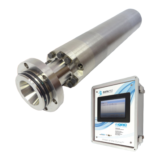
Data Pro The Data Pro is a high-performance universal configurable surface readout. The Data Pro can operate as a simple independent RTU and/or support internal SPS-1500 or FIC-1500 gauge interfaces. The main features are data logging, real-time graphing, historical graphing, Modbus communication, and gauge configuration. The Data Pro can be powered by either an AC or DC power supply and is enclosed in an NEMA-4X rated non-conductive, rust-proof enclosure with a transparent window and side latches. -
Page 30: Esp Sensors - Pass/Fail Criteria
APPENDIX 5 ESP Sensors - Pass/Fail Criteria All values must be taken at ambient conditions and the sensor allowed to stabilize if moved from a hot to cold or cold to hot environment for a period of one hour to confirm test validity. -
Page 31: Esp Sensors - Simpson Test Pass/Fail Criteria
All values must be taken at ambient conditions and the sensor allowed to stabilize if moved from a hot to cold or cold to hot environment for a period of one hour to confirm test validity. ESP-1500 Parameter Minimum Maximum Intake Pressure 0.1 psi 40 psi... -
Page 32: Esp Sensors - Megger Test Pass/Fail Criteria
ESP Sensors – Megger Test Pass/Fail Criteria All values in the table below are based on ambient conditions (70F, 14.7psia) using a FLUKE- 1550C. The testing equipment should be checked periodically to ensure the battery for the resistance test is at full capacity. If the sensor is above or below ambient conditions for storage such as being kept outside in the winter or summer then the sensor must be allowed to stabilize at room temperature (70F) for a period of one hour in order for the test measurement to be accurate. -
Page 33: Appendix 6 Sps-1500 Synchronization And Startup
APPENDIX 6 SPS-1500 Synchronization and Startup During the initial startup, the SPS tries to acquire the ESP gauge by performing a series of synchronization and analyzing steps. Below is typically what is displayed on the LCD screen, leaving out additional messages. The additional messages could contain any of the following text: “Okay”, “High Amp”, “Low Amp”, and “DC to DC Bad”. - Page 34 These steps might take anywhere from 2 to 5 minutes to complete. If data is not received after 5 minutes, proceed to the troubleshooting section of this manual. Note: During normal start-up and synchronization with the sensor you will see “Analyze 1”...
- Page 35 Sercel - GRC CORP 13914 E. Admiral Place, Ste. B Tulsa, Oklahoma 74116-2107/ USA Telephone : (1) 918 834 9600 Fax : (1) 918 838 8846 E-mail : sales@sercel-grc.com www.sercel-grc.com Produced according to the Sercel environmental printing standard...
Need help?
Do you have a question about the GRC ESP-Series and is the answer not in the manual?
Questions and answers