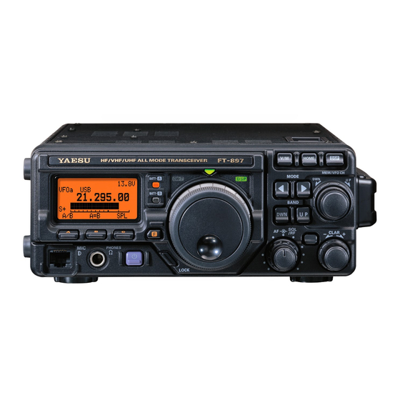
Yaesu FT-897 Manual
Alignment
Hide thumbs
Also See for FT-897:
- Technical supplement (146 pages) ,
- Operating manual (81 pages) ,
- Service manual (22 pages)
Table of Contents
Advertisement
Local
Oscillator
Reference Frequency Adjustment
a. Connect a frequency counter to TP1032.
b. Adjust the trimmer capacitor (TC5001) for 67.875000MHz ±5Hz on the frequency counter.
c. Connect a RF millivoltmeter or an oscilloscope to the J5002 2pin (TP1032) and confirm that the
output level is at least 70mVrms or 200mVp-p.
PLL Adjustment
VCO
VCV Adjustment
a. Connect a DC voltmeter to J2002 6pin (TP1028) and referring to the table below, tune the
transceiver to each frequency listed. Then con firm that the correct voltage is present, or adjust the
listed components for the required voltage.
Tune to :
13.895MHz
76.000MHz
32.995MHz
13.900MHz
55.995MHz
88.000MHz
163.995MHz
108.000MHz
469.995MHz
420.000MHz
1
st
Local Output Level
a. Connect a RF millivoltmeter to J2002 11pin and tune the transceiver to 28.000MHz.
b. Confirm that the RF level is at least +3dBm or 300mVrms.
PLL Unlock
a. Connect a DC voltmeter to J2002 1pin (TP1027).
b. When the reference input is not activated, the voltmeter shows less than 0.5V and
"UNLOCK" is displayed on the LCD.
c. When the reference input is activated, the voltmeter shows at least 3.5V and LCD displays
as it normally should do.
Idling Current Adjustment
Before alignment, set the mode on CW and tune the transceiver to 1.800MHz.
FT-897 Alignment
Adjustment
Adjust / Confirm
Adjust T2001
Confirm
Adjust T2002
Confirm
Adjust T2003
Confirm
Adjust L2010
Confirm
Adjust L2011
Confirm
For
5.5V ±0.5V
At least 0.8V
5.5V ±0.5V
At least 0.8V
5.5V ±0.1V
At least 0.8V
5.5V ±0.1V
At least 0.8V
5.5V ±0.1V
At least 0.8V
1
www.radioaficion.com
FT-897 Alignment
Vertex Standard Co., Ltd.
Advertisement
Table of Contents

Related Manuals for Yaesu FT-897


Summary of Contents for Yaesu FT-897
- Page 1 FT-897 Alignment FT-897 Alignment Local Oscillator Adjustment Reference Frequency Adjustment a. Connect a frequency counter to TP1032. b. Adjust the trimmer capacitor (TC5001) for 67.875000MHz ±5Hz on the frequency counter. c. Connect a RF millivoltmeter or an oscilloscope to the J5002 2pin (TP1032) and confirm that the output level is at least 70mVrms or 200mVp-p.
- Page 2 FT-897 Alignment Nothing should be connected to the CW Key Jack. Switch off the S1001. Pre-Driver Stage Idling Current a. Connect an ammeter at TP1019 and TP1010. b. Press the PTT and adjust VR1004 for an indication of 30mA ±2mA on the ammeter.
-
Page 3: Carrier Balance Adjustment
FT-897 Alignment b. Key the transmitter by FM mode and adjust T1014 for the maximum indication on the RF millivoltmeter. c. Connect a frequency counter to TP1008. d. Key the transmitter on FM m ode without microphone input. Adjust L1049 for 68.3300MHz ±100Hz. - Page 4 FT-897 Alignment output, 1KHz AF FM modulation of 3.5 KHz deviation. b. Adjust T1024, T1026, and T1028 alternately for the best SINAD sensitivity. c. Increase the output level of the signal generator up to 12dBu approximately and adjust T1024 and T1026 alternately for the best SINAD s ensitivity.
-
Page 5: V/Uhf Idling Current Adjustment
FT-897 Alignment Power Amplifier Adjustment HF/50MHz Idling Current Adjustment a. Connect an ammeter at TP3021 and TP3022. b. Turn both VR3002 fully to counterclockwise. c. Press the PTT and adjust VR3002 for an indication of 300mA ±10mA on the ammeter. -
Page 6: Rx Gain Adjustment
FT-897 Alignment RX Gain Adjustment a. Select the CW mode. Tune the transceiver to 1.8MHz band. Select "HF1RXG" in the menu by rotating VFO/M-CH knob. Inject a RF signal from a signal generator at 2dBu output. b. Set the parameter "HF1RXG" at the value of lighting the first dot of the S-meter (S1) on the LCD by rotating the main dial. -
Page 7: Fm Squelch Adjustment
FT-897 Alignment FM Squelch Adjustment a. Tune the transceiver to 144MHz band on FM m ode. Confirm that the squelch knob is turned to fully counterclockwise. b. Select the menu item "FM-TH1" and press [A] key without antenna input to set the parameter. -
Page 8: Tx Gain Adjustment
FT-897 Alignment 2W. In case the transmission power is not within the tolerance, adjust the parameter for 20W ± 2W transmission power. h. Select the menu item "VHF-MIN". Key down and confirm that the output power is 5W ±... -
Page 9: Carrier Level Adjustment
FT-897 Alignment parameter for 10W transmission power. Carrier Level Adjustment a. Tune the transceiver to 21MHz band. Connect a 50 dummy load to the antenna connector. Set the mode on CW. Select the menu item "CW -CAR" and key the transceiver.
Need help?
Do you have a question about the FT-897 and is the answer not in the manual?
Questions and answers