Table of Contents
Advertisement
To buy, sell or trade in this product click on the link below:
http://www.avionteq.com/Barfield-CT12A-Digital-Cable-Tensiometer-PN-101-03100.aspx
Corporate Headquarters
4101 Northwest 29th Street
Miami, Florida 33142
www.barfieldinc.com
Email: gsesales@barfieldinc.com
www.avionteq.com
CT12A
Digital Cable Tensiometer
USER INSTRUCTION MANUAL
BARFIELD M/N CT12A
Doc. P/N: 56-101-03100
Revision E
May 29, 2009
______________________________________
BARFIELD, INC.
Advertisement
Table of Contents

Related Manuals for barfield CT12A


Summary of Contents for barfield CT12A
- Page 1 To buy, sell or trade in this product click on the link below: http://www.avionteq.com/Barfield-CT12A-Digital-Cable-Tensiometer-PN-101-03100.aspx www.avionteq.com CT12A Digital Cable Tensiometer USER INSTRUCTION MANUAL BARFIELD M/N CT12A Doc. P/N: 56-101-03100 Revision E May 29, 2009 ______________________________________ BARFIELD, INC. Corporate Headquarters 4101 Northwest 29th Street Miami, Florida 33142 www.barfieldinc.com...
- Page 3 CT12A INSTRUCTION MANUAL This page intentionally left blank. 56-101-03100-E Blank May / 29 / 09 Page ii...
- Page 4 CT12A INSTRUCTION MANUAL This page intentionally left blank. 56-101-03100-E Blank May / 29 / 09 Page iii...
- Page 5 CT12A INSTRUCTION MANUAL CONTACT INFORMATION Users are requested to notify the manufacturer of any discrepancy, omission, or error found in this manual. Inquiries should include specific questions and reference the publication title, number, chapter, page, figure, paragraph, and effective date.
- Page 6 CT12A INSTRUCTION MANUAL This page intentionally left blank. 56-101-03100-E Blank May / 29 / 09 Page v...
- Page 7 Although every effort has been made to provide the end user of this equipment with the most current and accurate information, it may be necessary to revise this manual in the future. Please be sure to complete and return a Revision Request Form to Barfield revision services and visit the company website, http://barfieldinc.com/, for publication updates.
- Page 8 CT12A INSTRUCTION MANUAL This page intentionally left blank. 56-101-03100-E Blank May / 29 / 09 Page vii...
- Page 9 Users are recommended to consult their aircraft maintenance manual or the like in accordance to cable tension rigging procedures. Pictorial representations of the CT12A are similar to but not necessarily identical to that of the physical unit. Figures and diagrams are presented for reference only.
- Page 10 CT12A INSTRUCTION MANUAL This page intentionally left blank. 56-101-03100-E Blank May / 29 / 09 Page ix...
- Page 11 Jul / 05 / 06 Initial Release. Revisions made to reflect disclaimer, additional 260-00681 Oct / 11 / 06 cautionary notes for CT12A use and options in calibration services. Revisions made to reflect new CT12A lever design 260-00697 May / 17 / 07 and Averaging Mode feature and operation.
- Page 12 CT12A INSTRUCTION MANUAL This page intentionally left blank. 56-101-03100-E Blank May / 29 / 09 Page xi...
- Page 13 CT12A INSTRUCTION MANUAL LIST OF APPROVED REPAIR FACILITIES The manufacturer of this equipment does not recommend the user to attempt any maintenance or repair. In case of malfunction, contact the manufacturer, to obtain the list of approved repair facilities worldwide, ensuring that this equipment will be serviced using proper procedures and certified instruments.
- Page 14 CT12A INSTRUCTION MANUAL This page intentionally left blank. 56-101-03100-E Blank May / 29 / 09 Page xiii...
-
Page 15: Table Of Contents
POWERING ON THE UNIT AND INTRODUCTORY DISPLAY ....11 SELECTION OF THE OPERATING MODE ..........11 TAKING A TEMPERATURE READING ............12 SETTING THE DISPLAY BACKLIGHT ............12 SETUP OF CT12A FOR TAKING TENSION MEASUREMENTS ....13 TAKING TENSION MEASUREMENTS............14 HOLDING A TENSION MEASUREMENT ...........16 USE OF THE VERIFICATION BAR ............16 POWERING OFF THE CT12A ..............18... - Page 16 CT12A INSTRUCTION MANUAL This page intentionally left blank. 56-101-03100-E Blank May / 29 / 09 Page xv...
- Page 17 Figure 3: Limited Warranty Statement Card ..................2 Figure 4: CT12A multi-cable unit ......................5 Figure 5: Front view of single-cable CT12A unit .................7 Figure 6: Front view of multi-cable CT12A unit ...................8 Figure 7: Two views of the correct placement of the Verification Bar ..........17 Figure 8: CT12A with Battery Charger Accessory ................
- Page 18 CT12A INSTRUCTION MANUAL This page intentionally left blank. 56-101-03100-E Blank May / 29 / 09 Page xvii...
-
Page 19: Introduction
CT12A INSTRUCTION MANUAL INTRODUCTION 1. PUBLICATION BREAKDOWN This user instruction manual establishes the standards of operation for Barfield’s CT12A Digital Cable Tensiometer. 2. INFORMATION PROVIDED WITH THE UNIT Besides this User Instruction Manual, the Tensiometer is provided with the four items de- scribed below. - Page 20 CT12A INSTRUCTION MANUAL B. The Owner's Warranty Registration card (Figure 2) is to be completed by the owner and returned to Barfield, Inc. within ten (10) days of purchase to ensure automatic update of printed matter and validation of warranty.
-
Page 21: Recertification
3. RECERTIFICATION The Barfield CT12A Digital Cable Tensiometer and its Verification Bar have a one-year recertification requirement. Qualified technicians in a shop equipped with the necessary tooling and facilities must perform the maintenance required by this unit. - Page 22 CT12A INSTRUCTION MANUAL This page intentionally left blank. 56-101-03100-E Blank May / 29 / 09 Page 4 of 19...
-
Page 23: Product Description
The Barfield CT12A Digital Cable Tensiometer was designed to meet the industry’s requirements for testing and measuring the tension of aircraft cables. The CT12A measures the existing tension in cables, in diameters from 1/16” to 1/4”. Two dif- ferent unit types are available within the product line: multi-cable and single-cable. Multi- cable units can measure up to seven different cable sizes, while single-cable units are cus- tomized for one specific cable size. -
Page 24: Ct12A Features
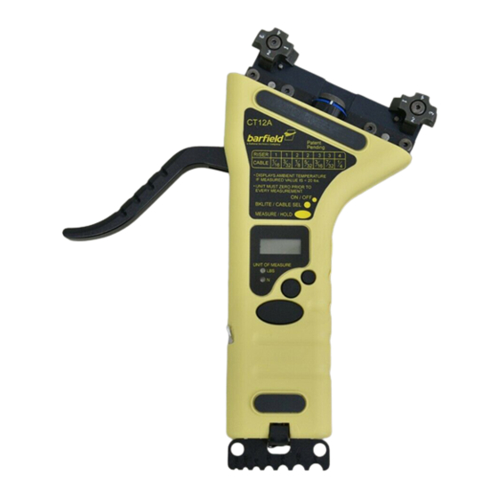
Standard Mode and Averaging Mode options • Cable readings adjusted to pounds or Newtons during calibration stage* 3. PHYSICAL DESCRIPTION Table 1: CT12A Components Description, referred to Figs. 5 and 6. Name Description and Function Riser Grips cable under test. - Page 25 Lever [3] PC port [10] Battery charger port [9] Skid [11] Cable gauge [12] Figure 5: Front view of single-cable CT12A unit (component numbers indicated in Table 1). 56-101-03100-E CH. 1 May / 29 / 09 Page 7 of 19...
- Page 26 Lever [3] PC port [10] Battery charger port [9] Skid [11] Cable gauge [12] Figure 6: Front view of multi-cable CT12A unit (component numbers indicated in Table 1). 56-101-03100-E CH. 1 May / 29 / 09 Page 8 of 19...
-
Page 27: Product Specifications
Barfield performs custom calibrations using other cables for an additional charge, on the condition that they do not have plastic jacket, this is, that they do not belong to type II. -
Page 28: Specifications For Ct12A Model Numbers
CT12A INSTRUCTION MANUAL 6. SPECIFICATIONS FOR CT12A MODEL NUMBERS Table 2: Descriptions and Measurement Specifications according to Model Numbers. Model Cable Range Tolerance Description Riser/Pos. Number Size (Lbs.) (Typ.) (Lbs.) ± 4 25-100 102-03101 Single Cable Tensiometer for 1/16" Diameter 1/16"... -
Page 29: Operation
POWERING ON THE UNIT AND INTRODUCTORY DISPLAY Securely hold the CT12A unit in the palm of your hand. Turn the instrument on by pressing and holding down the ON / OFF button until the display activates. -
Page 30: Taking A Temperature Reading
Averaging Mode to ensure the reliability of the measurement. When the CT12A is powered On, the unit defaults to the Mode in which it was during its last use. The unit is shipped after being set by the manufacturer to Standard Mode. -
Page 31: Setup Of Ct12A For Taking Tension Measurements
The preparation for taking tension measurements depends on the CT12A configuration. If the CT12A to be used is of the single-cable type (as described in Section 1): Determine the cable size. If needed, use cable gauge provided at one end of the CT12A. -
Page 32: Taking Tension Measurements
After these settings are completed, press and release the MEASURE / HOLD button and move the lever. CT12A will show the ambient temperature, indicating that the set up is complete, so the unit is ready to start taking measurements. - Page 33 CT12A is ready to measure when the LED stops blinking. Clamp the CT12A to the cable to be tested, making sure the risers are seated on the ca- ble, by pushing the lever completely against the body. A blinking LED means that the CT12A is measuring the cable's tension.
-
Page 34: Holding A Tension Measurement
The Hold feature is especially helpful when the dis- play is not in the line of sight, such that the user will need to remove the CT12A from the cable to take the reading. The value in the display window will remain frozen until the MEASURE / HOLD button is pressed again to release the Hold Mode. - Page 35 Hint: If quick check is not within tolerance, then perform verification in average mode. Place the Verification Bar on risers as shown in Fig. 7. Figure 7: Two views of the correct placement of the Verification Bar in the CT12A 56-101-03100-E CH. 3...
-
Page 36: Powering Off The Ct12A
Connect the battery charger to a 115 VAC 50 / 60 Hz power source. Lift the rubber cover of the charger port, located at the bottom edge of the CT12A (Fig. 8), and insert there the battery charger cable connector as shown. -
Page 37: Receiving, Shipping, And Storage
CT12A. Also recommended is that the CT12A be carefully inspected for damage. Check for any binding of moving parts, improper mountings, broken parts and any other condition that may affect operation.
Need help?
Do you have a question about the CT12A and is the answer not in the manual?
Questions and answers