
Related Manuals for Caen ELS OCEM NGPS series

Summary of Contents for Caen ELS OCEM NGPS series
- Page 1 NGPS – User’s Manual NGPS High-Stability and High-Precision New Generation Power Supply Series User’s Manual All Rights Reserved © CAEN ELS s.r.l. & Energy Technology s.r.l. Rev. 1.6 – October 2019...
- Page 2 NGPS – User’s Manual CAEN ELS s.r.l. Energy Technology s.r.l. via Vetraia, 11 via della Solidarieta’, 2/1 55049 Viareggio (LU) – Italy 40056 Valsamoggia (BO) – Italy Mail: info@caenels.com Mail: power@ocem.com Web: www.caenels.com Web: www.ocem.eu...
- Page 3 NGPS-CMD 300-30E ** These models are not fully compatible with “Remote Control Manual” from CAEN ELS S.r.l., are not compatible with other Firmwares other than the factory one, and support for these models must be required at: support.pe@ocem.eu In general, this manual also covers the basic functions of Custom Model named as...
- Page 4 NGPS – User’s Manual...
-
Page 5: Table Of Contents
NGPS – User’s Manual Table Of Contents INTRODUCTION ....................12 NGPS O ..................12 VERVIEW NGPS ..................15 AT A GLANCE .................. 17 ODES OF PERATION Regulation Mode ..................17 Control Mode ................... 17 Update Mode .................... 18 ..............19 NTERLOCK AND STATUS IGNALS Interlock Enable/Disable Mask .............. - Page 6 NGPS – User’s Manual Config Page ..................52 Advanced Page ................. 53 SOFTWARE COMMANDS ................55 .................. 55 THERNET NTERFACE ..................55 OMMAND YNTAX ..................56 OMMAND EPLIES ....................58 RROR ABLE ..................59 OMMAND ABLE ..................62 ASIC OMMANDS MON Command ..................
- Page 7 NGPS – User’s Manual Document Revisions Document Revision Date Comment February 7 2016 Draft Release February 22 2016 Pre Release Version March 15 2016 Visual PS information added and corrected May 27 2016 Added Safety Information and Installation Chapter 2. Removed parts from Introduction and Chapter 1 September 1...
- Page 8 NGPS – User’s Manual Safety information The following table shows the general environmental requirements for a correct operation of instruments referred in this User’s Manual: Environmental Conditions Requirements Environment Indoor use Operating Temperature 0°C to 40°C Operating Humidity 20% to 80% RH (non-condensing) Altitude Up to 2000 m Pollution degree...
- Page 9 User. It is strongly recommended to read thoroughly this User's Manual before any kind of operation. CAEN ELS s.r.l. and Energy Technology s.r.l. reserve the right to change partially or entirely the contents of this Manual at any time and without giving any notice.
- Page 10 NGPS – User’s Manual Disposal of the Product The product must never be dumped in the Municipal Waste. Please check your local regulations for disposal of electronics products.
- Page 11 NGPS – User’s Manual WARNING • Do not use this product in any manner not specified by the manufacturer. The protective features of this product may be impaired if it is used in a manner not specified in this manual. •...
-
Page 12: Introduction
High performances, high efficiency, high stability, easiness of configuration and maintenance are the key features of the NGPS power supply series, generated by the joint effort of CAEN ELS and OCEM – Power Electronics. The NGPS is an independent current- or voltage-controlled digital monopolar power supply module. - Page 13 NGPS – User’s Manual Installation Model Name Current (A) Voltage (V) Max. Power (kW) NGPS 100-100E NGPS 120-50E NGPS 140-50E NGPS 150-70E 10.5 NGPS 200-50E NGPS 200-40E NGPS 200-30E NGPS 200-60E NGPS 300-25E NGPS 300-30E NGPS 400-30E NGPS-CAX 100-100E NGPS-CAX 200-40E NGPS-CAX 200-50E NGPS-CVF 30-300E Table 1a: Standard NGPS models...
- Page 14 NGPS – User’s Manual Installation Table 1b: Customized NGPS models The NGPS units are available in three different values of nominal three-phase input voltage: Version Three-Phase Input “A” 208 V (AC) “E” 400 V (AC) “U” 480 V (AC) Table 2: NGPS versions The NGPS module is composed of a single 19-inch standard crate.
-
Page 15: Ngps At A Glance
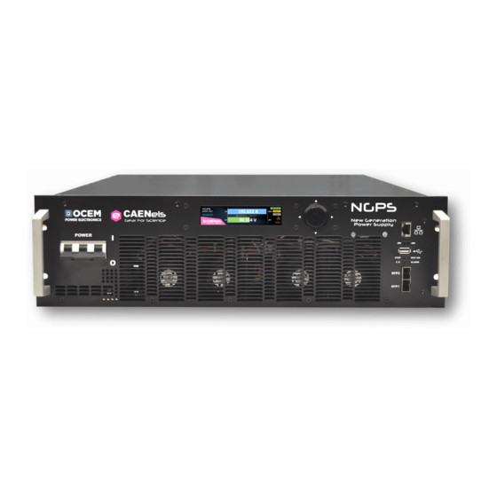
NGPS – User’s Manual Installation 1.2 NGPS at a glance The standard NGPS system is composed by a single 19-inch 3U crate. The NGPS unit and its I/O connections can be easily seen in Figure 1 (front view) and Figure 2 (rear view). - Page 16 NGPS – User’s Manual Installation Custom models may mount additional I/O connectors; these cases are covered in section 1.11.
-
Page 17: Modes Of Operation
NGPS – User’s Manual Installation 1.3 Modes of Operation The NGPS system has multiple features and multiple configurations that allow using the unit for a very widespread topology of applications. A brief summary of the basic configurations that the unit is able to handle are hereafter presented. -
Page 18: Update Mode
NGPS – User’s Manual Installation Update Mode The current or voltage setting of the unit can also be performed in four different modes: • NORMAL: the update of the set-point (current or voltage, depending on the operation mode) is performed as soon as a new set-point is received via the remote, local or fast interfaces;... -
Page 19: Interlock And Status Signals
NGPS – User’s Manual Installation 1.4 Interlock and status Signals The NGPS module has four configurable dry-contact input interlocks and two output status signals that are directly available on the D-Sub 15 Pin Female connector on the rear panel (Figure 3). A mating connector, a standard D-Sub 15 Pin Male type, can be installed in order to use/access these available signals. - Page 20 NGPS – User’s Manual Installation WARNING Magnetic Relay Contact ( C-TAP, NO-TAP & NC-TAP) and shall not float Solid State Relay Terminals (Terminal #1 & #2) more than ±60VDC above/below chassis ground. Interlocks input and return pins shall not float more than ±60VDC above/below chassis ground.
-
Page 21: Interlock Enable/Disable Mask
NGPS – User’s Manual Introduction Interlock Enable/Disable Mask The NGPS series external interlock can be enabled or disabled by writing to the corresponding Interlock Enable/Disable Mask field of the advanced configuration parameters (field #90), using the MWG command. The value to be written is in ASCII format, representing the corresponding bit mask, as shown in the following table: Bit #4 Bit #3... -
Page 22: Interlock Identification Name
NGPS – User’s Manual Introduction fault condition). The Intervention time parameters are stored in the field #92 for Interlock #1, in field #94 for interlock #2, in field #96 for interlock #3 and in field #98 for interlock #4. The value to be set is in ASCII format, representing the intervention time in milliseconds. -
Page 23: Remote Sensing
NGPS – User’s Manual Introduction 1.5 Remote Sensing WARNING There is a potential shock hazard at the sense point when using power supply with rated output voltage greater than 60 V. Moreover, even at output voltages lower than 60 V the energy hazard is always present due to the high current capability of the unit. - Page 24 NGPS – User’s Manual Introduction The two remote sensing terminals are present on the corresponding connector on the rear panel: Description Name SENSE – – – –S SENSE Table 7: Remote sensing pinout By using these two “sensing” pins it is possible to sense the output voltage directly on the load, thus recovering possible voltage drops on the output cables up to It is strongly suggested to use twisted cables when using the remote sensing feature in order to minimize possible noise pick-up.
- Page 25 NGPS – User’s Manual Introduction In order to perform remote sensing at different points – e.g. the load terminals – it would be necessary to connect Pin #1 and Pin #4 as in Figure 6 NGPS Power Cables OUTPUT CONNECTOR Sensing Cables Figure 6: Example of Remote Sensing...
-
Page 26: Trigger And Analog Control Inputs
NGPS – User’s Manual Introduction 1.6 Trigger and Analog Control inputs On the rear side of the NGPS there are two BNC input connectors, as shown in Figure 7, which can be used as trigger and analog control inputs. Figure 7: Trigger and Analog input connectors Trigger input The trigger input accepts TTL (5V) and LVTTL (3.3V) compatible signals and should be driven by a low-impedance source or generator. -
Page 27: Analog Control Input
NGPS – User’s Manual Introduction Trigger Input ABSOLUTE MAXIMUM Trigger Signal HIGH LEVEL LOW LEVEL Figure 8: Trigger Thresholds Analog Control input The analog control input allows controlling the NGPS unit as an “amplifier”. This input is labelled as “AN CTRL”. This input accepts signals ranging from 0V to +10V and generates an output which is proportional to the input signal, zero output for a 0V input and Full-Scale output for a +10V input. -
Page 28: Front Panel Indicators
NGPS – User’s Manual Introduction 1.7 Front Panel Indicators The NGPS has four (4) front panel LED indicators as shown in the following Figure 10 Figure 10: front panel indicators The front panel indicators and their behaviour are hereafter listed (clockwise starting from top-left): •... -
Page 29: Earth Leakage Current
NGPS – User’s Manual Introduction Earth Leakage Current This protection continuously monitors the current flowing to earth and it has a settable threshold [A] that can be set by experienced users. The tripping of this protection generates a fault condition that shuts the power supply output off. Earth Fuse An earth fuse is present on the rear side of each NGPS and it is rated at 5A, 500 V (F5AH500VAC). -
Page 30: Overpower - Ovp
NGPS – User’s Manual Introduction A typical example of a regulation fault is represented by a 1Ω load on a NGPS 200-50 for example where the maximum power supply output voltage is 50V. By setting a current of 100A to the load, the output voltage should reach a value of 100V which obviously is not feasible: once the power unit supplies 50A to the load it already reaches the maximum output voltage condition. -
Page 31: Dc-Link Undervoltage
NGPS – User’s Manual Introduction The threshold value [°C] can be set by experienced users. A reset fault operation needs to be executed on the status register of the NGPS before turning the output off again. DC-Link Undervoltage The NGPS is composed internally by a power AC-DC section cascaded with a DC-DC stage. -
Page 32: Status Register
NGPS – User’s Manual Introduction 1.10 Status Register The following table shows the NGPS internal status register structure: Bit # Bit name Description Over Power condition DCCT FAULT DCCT Not working properly Ext. Interlock #4 External interlock 4 has tripped Ext. -
Page 33: Custom Models
NGPS – User’s Manual Introduction 1.11 Custom Models This section covers peculiars features provided in specific models only; NGPS-AUX yyy-zzzK NGPS-AUX models are common custom models provided with an additional single-phase input connector on the rear side: Figure 12: NGPS-AUX additional single-phase input The auxiliary 230 VAC, 1-phase input connector is a plug filter with switch and fuse-box, provided with two interchangeable fuses 5x20 rated at 2A. -
Page 34: Installation
Keep all packing material until the inspection has been completed. If damage is detected, compile the RMA form available to the CAEN ELS web site. 2.3 Mounting The NGPS is a rack-mount device since the unit form factor is designed to be installed in a standard 19-inch cabinet. - Page 35 NGPS – User’s Manual Local Control CAUTION The unit(s) shall be installed assuring that the main circuit breaker present on the front panel can be always easily operated by user personnel. CAUTION This power supply is fan cooled, the air intake is at the front panel and the exhaust is at the rear panel.
-
Page 36: Ac Input Power Connection
NGPS – User’s Manual Introduction 2.4 AC Input Power Connection CAUTION Connection of this power supply to an AC power source should be made by an electrician or other qualified personnel. Do not exceed the torque specified on input stud terminals. - Page 37 NGPS – User’s Manual Local Control Recommended Cable Size for Input Connection are listed in Recommended copper Input voltage Current RMS per phase wire size 208 V 34 A 6 mm 400 V 18 A 4 mm 480 V 16 A 4 mm Table 12: AC Cable size The AC input current and voltage rating is marked on the rear terminal of the...
- Page 38 NGPS – User’s Manual Introduction Figure 14: Protective cover mounting Figure 15: AC Mains cable fastener For safety reasons, the mains supply voltage ratings should not exceed the indicated voltage range.
-
Page 39: Ac Source Requirement
NGPS – User’s Manual Local Control AC Source requirement The NGPS power supplies are designed for 208 V AC, 400 V AC or 480 V AC input range depending on the model; frequency ranging from 47 Hz to 63 Hz. Installation Category shall be CAT II so maximum impulse voltage on the network mains must be below 2500 V. - Page 40 NGPS – User’s Manual Introduction Maximum Cable length in meters to limit voltage drop to be less than 2 V (1 V per lead) Wire Cross Resistivity [Ω/km] Section Area @ 20°C 120 A 200 A 300 A 0.524 0.387 0.268 18,5 0.193...
-
Page 41: Grounding Outputs
NGPS – User’s Manual Local Control Figure 16: Output terminal connections (insert screw and secure it) The symbols “+” and “-” on the rear panel indicate the positive and negative polarity of the terminal respectively. After securing both output connections it is necessary to mount the metallic protective cover since the power supply has the capability of delivering a high current on these outputs and/or hazardous voltage for NGPS with output voltage ratings >... -
Page 42: Parallel Operation
NGPS – User’s Manual Introduction If accidentally one of the output terminals is conducting to the Protective Ground a fault will be triggered switching the power supply Off. Refer to Earth Fuse Fault and Earth Leakage Fault. To allow floating operation of the output it is sufficient to remove the Earth Fuse from the fuse-holder and set the Power supply for Floating operation (refer to section 4.7.1). - Page 43 NGPS – User’s Manual Local Control CAUTION Use a support bar to provide adequate support for the power supply. 2. Connect the output terminals in parallel, i.e. positive with positive and negative with negative. Below an example of a 2 NGPS and a 4 NGPS system: In order to parallel the output terminals, bar connections (as in the pictures above) have to be preferred over cable connections.
- Page 44 NGPS – User’s Manual Introduction 3. Connect the modules SFP transceivers in daisy-chain mode: SFP plug-ins and optical cables already prepared in order to respect the daisy-chain will be shipped together with the modules to be paralleled. Being a daisy-chain, the user can connect the optical cables plugs to SFP plugins in any order.
- Page 45 NGPS – User’s Manual Local Control MASTER SLAVE(S) CONFIGURATION 1. Per each NGPS use the local control mode and select “Advanced”: 2. In the “Advanced” window, select “Parallel”; 3. The NGPS with the earth fuse has to be selected as “Master” and the OFF/ON selection on “ON”: After that, press “Return”.
-
Page 46: Local Control
NGPS – User’s Manual Introduction 3. Local Control This chapter describes the local control functionalities that are provided by the NGPS power supply and some useful information on how to use it. The power supply can work either in LOCAL mode or in REMOTE mode. Please note that only readbacks are allowed from the remote communication interfaces when the unit is in LOCAL mode (i.e. -
Page 47: Display
NGPS – User’s Manual Local Control 3.2 Display The colour display on the NGPS power supply unit allows users to visualize information about the power supply status and to control the unit in order to use it locally. Screens and pages of the display can be navigated from the navigation switch though user friendly menus and sub-menus. -
Page 48: Home Screen
NGPS – User’s Manual Local Control Home Screen The NGPS home screen is the first loaded page upon power-up or power-cycling of the module, it is shown in , and contains information on: Figure 19 • the NGPS model; • the module IP address; •... - Page 49 NGPS – User’s Manual Local Control By pushing the Up arrow pushbutton of the Navigation Switch, the Home Screen turns from showing the output current and voltage measurement to showing the current and voltage Set Points. The sign “SET POINT” substitutes the module identification name.
-
Page 50: Menu Page
NGPS – User’s Manual Local Control Menu Page The Menu page is reachable by performing any action on the navigation switch when in the Home Screen. The Menu Page gives access to all the local features of the NGPS power supply unit. -
Page 51: Control Page
NGPS – User’s Manual Local Control Control Page The Control Page is reachable by selecting the corresponding rectangle from the Menu Page. The Control Page gives access to the main settings of the NGPS power supply unit. An example of a Control Page visualization is shown in Figure 22 Figure 22: Control Page From this screen it is possible to turn the power supply unit ON and OFF and to... -
Page 52: Config Page
NGPS – User’s Manual Local Control Config Page The Config Page is reachable by selecting the corresponding rectangle from the Menu Page. This page allows the user to set the control mode of the power supply – e.g. LOCAL or REMOTE – to select the regulation mode (C.C. or C.V.) and to set the ethernet (NORM) or analog (AIN) control. -
Page 53: Advanced Page
NGPS – User’s Manual Local Control Advanced Page The Advanced Page is reachable by selecting the corresponding rectangle from the Menu Page. This page allows selecting further sub-pages: Figure 24: Advanced Page • Network Page This page allows to locally set the power supply Ethernet IP address, the Network Mask and the Gateway. - Page 54 NGPS – User’s Manual Local Control • > allows to select further sub-pages Figure 27: Advanced Page – second selection page • System info Shows internal temperatures and CPU usage. Figure 28: System info Page REMARK: o “Heatsink 1 temp” is the maximum temperature between the IGBT module heatsink temperature and the output rectifier module heatsink temperature o “Heatsink 2 temp”...
-
Page 55: Software Commands
– User’s Manual NGPS Software Commands 4. Software Commands This chapter describes the base TCP/IP software commands used for the control and configuration of the NGPS power module. 4.1 Ethernet Interface The device is shipped with default IP address, subnet mask, and gateway and TCP-IP communication port: Parameter Factory Value... -
Page 56: Command Replies
– User’s Manual Software Commands NGPS Command Example: MWI:20.5580\r\n • “MWI” is the command field; • “:” is the parameter’s separation character; • “20.5580” is the first parameter field; • “\r\n” is the termination sequences of the command. Commands are processed one at a time; therefore user must wait for a response from the unit before sending the next command. - Page 57 – User’s Manual NGPS Software Commands • “#NAK” is the Not AcKnowledged response to an invalid command; • “:” is the parameter’s separation character; • “01” is the error code, • “\r\n” is the termination sequence of the reply. For read commands, the replies are generally formed by an echo string, followed by the corresponding read value.
-
Page 58: Error Table
– User’s Manual Software Commands NGPS 4.4 Error Table The list of error codes returned with the #NAK reply and their description are hereafter shown: Error Code # Description Unknown command Unknown Parameter Index out of range Not Enough Arguments Privilege Level Requirement not met Saving Error on device Invalid password... -
Page 59: Command Table
– User’s Manual NGPS Software Commands 4.5 Command Table The list of commands used by the NGPS and the corresponding syntax is hereafter presented as well as a description of each command purpose and any special requirements related to the specific command. The base commands are summarized in the following table:... - Page 60 NGPS – User’s Manual Software Commands Read/ Command Parameter #1 Parameter #2 Detailed description Reply value Write Return the module model and installed firmware ASCII indicating the module model and firmware versions version “AK” or “NAK” Turn on the module “AK”...
- Page 61 NGPS – User’s Manual Software Commands Read/ Command Parameter #1 Parameter #2 Detailed description Reply value Write Read estimated active output power value [W] ASCII indicating the active output power value Read leakage current value [A] ASCII indicating the Leakage voltage value MRID Read module identification Module identification (ASCII)
-
Page 62: Basic Commands
– User’s Manual Software Commands NGPS 4.6 Basic Commands In the following section are described the basic commands that allow to control the NGPS unit and to monitor its status. MON Command The MON (Module ON) command is intended to turn ON the NGPS output driver, thus enabling the output current terminals and allowing the power supply to regulate and feed current or voltage to the connected load. -
Page 63: Moff Command
NGPS – User’s Manual Software Commands MOFF Command The MOFF (Module OFF) command is intended to turn OFF the NGPS output driver, thus disabling the output terminals. The MOFF command automatically sets output current to 0A or 0V with a ramp before disabling the output drivers. -
Page 64: Ver Command
– User’s Manual Software Commands NGPS VER Command The VER command returns the information regarding the NGPS model and the current installed firmware version. The response to the VER command is in the following format: #VER:ps_model:fw_version\r\n where “#VER” is the echo string, “ps_model” is the NGPS model and “fw_version” is the current firmware version. -
Page 65: Mst Command
NGPS – User’s Manual Software Commands MST Command The MST command returns the value of the NGPS power supply internal status. The response to the MST command is in the following format: #MST:status_reg\r\n where “#MST” is the echo string and “status_reg” is the hexadecimal representation of the internal status register. -
Page 66: Mreset Command
– User’s Manual Software Commands NGPS MRESET Command The MRESET command has to be used in order to perform a complete reset of the module status register. This is needed, for example, to enable the channel output again after a fault condition has been fixed. Replies from the NGPS to a MRESET command are in the form “#AK\r\n”... -
Page 67: Mri Command
NGPS – User’s Manual Software Commands MRI Command The MRI command returns the readback value of the power supply actual output current. The readback current value is represented with 6-digit precision. Replies from the power supply to this command are in the following format: #MRI:current_value\r\n where “#MRI”... -
Page 68: Mrv Command
– User’s Manual Software Commands NGPS MRV Command The MRV command returns the readback value of the power supply actual output voltage. The voltage readback value is represented with 6-digit precision. Replies from the power supply to this command are in the following format: #MRV:voltage_value\r\n where “#MRV”... -
Page 69: Loop Command
NGPS – User’s Manual Software Commands LOOP Command The LOOP command can be used in order to select the mode of loop control of the NGPS unit. There are two possible modes of operation: • Constant Current (c.c.), • Constant Voltage (c.v.). To set the mode of operation the following commands has to be used: LOOP:mode\r\n where “mode”... -
Page 70: Mwi Command
– User’s Manual Software Commands NGPS MWI Command The MWI command can be used to set the output current value when the module is in the constant current mode (see LOOP Command). This command is usually needed when running feedback-related applications and for small changes in the output current. The use of this command is alternative to the MWIR Command (ramping current command), which is advised for regular use. -
Page 71: Mwv Command
NGPS – User’s Manual Software Commands MWV Command The MWV command can be used to set the output voltage value when the constant voltage mode is used (see LOOP Command). The use of this command is alternative to the MWVR Command (ramping voltage command). This command has the following format: MWV:voltage_setpoint\r\n where “voltage_setpoint”... -
Page 72: Mwir Command
– User’s Manual Software Commands NGPS MWIR Command The MWIR command can be used to perform a ramp to the given current setpoint. This command can be used, when the constant current mode is selected (see LOOP Command). The use of this command is alternative to the MWI Command. The difference between the MWI command and the MWIR command is that the first one generates a direct change in output current characterized by the PID regulator parameters (the command is ideally suited for small output current changes and feedback purposes) - Page 73 NGPS – User’s Manual Software Commands MWIR query example: MWIR:?\r\n #MWIR:10.5\r\n...
-
Page 74: Msri Command
– User’s Manual Software Commands NGPS MSRI Command The MSRI command can be used to dynamically change the value of the current ramp slew-rate. The default slew-rate, used at start-up of the unit, is the value stored in the parameters table. This command has the following format: MSRI:slew_rate\r\n where “slew_rate”... -
Page 75: Mwvr Command
NGPS – User’s Manual Software Commands MWVR Command The MWVR command can be used to perform a ramp to the given voltage setpoint. This command can be used, when the constant voltage mode is selected (see LOOP Command). The use of this command is alternative to the MWV Command. The difference between the MWV command and the MWVR command is that the first one generates a direct change in output voltage characterized by the PID regulator parameters while the second one makes the power supply go from the previous to the actual current value... - Page 76 – User’s Manual Software Commands NGPS MWVR query example: MWVR:?\r\n #MWVR:15.2\r\n...
-
Page 77: Msrv Command
NGPS – User’s Manual Software Commands MSRV Command The MSRV command can be used to dynamically change the value of the voltage ramp slew-rate. The default slew-rate, used at start-up of the unit, is the value stored in the parameters table. This command has the following format: MSRV:slew_rate\r\n where “slew_rate”... -
Page 78: Mrt Command
– User’s Manual Software Commands NGPS MRT Command The MRT command returns the value of the maximum temperature between the maximum between the temperatures of the two air cooled heatsinks (shown on the local interface, in the Advanced page “System info” as Heatsink 1 temperature) and the temperature directly measured on the HF transformers (shown on the same “System info”... -
Page 79: Mrw Command
NGPS – User’s Manual Software Commands MRW Command The MRW command returns the actual value of the estimated active power applied to the connected load. The response to the MRW command is in the following format: #MRW:active_power\r\n where “#MRW” is the echo string and “active_power” is the output active power readback expressed in Watts [W], estimated as the product of the output voltage and output current readbacks. -
Page 80: Mgc Command
– User’s Manual Software Commands NGPS MGC Command The MGC command returns the readback value of the actual leakage current of the NGPS unit. The response to the MGC command is in the following format: #MGC:leakage_current\r\n where “#MGC” is the echo string and “leakage_current” is the earth leakage current, expressed in Ampere [A]. -
Page 81: Mrid Command
NGPS – User’s Manual Software Commands MRID Command The MRID command returns the NGPS identification name string. This description is useful in case that there are numerous units installed and it is possible to give a description for each unit (for example the name of the load on which the unit is connected). -
Page 82: Configuration Commands
– User’s Manual Software Commands NGPS 4.7 Configuration Commands In the following section are described the software commands that allow to read, set and store the working parameters of the NGPS unit. The MRG Command and MWG Command allow to read or modify the working parameters. - Page 83 NGPS – User’s Manual Software Commands Parameter Access Privileges Parameter Name User Default Current Slew Rate [A/s] User Default Voltage Slew Rate V [V/s] #33 - #34 Reserved Admin TFT Timeout [minutes] Read Only Feed Forward enabled #37 - #39 Reserved Admin PID I: Kp_v...
-
Page 84: Mrg Command
– User’s Manual Software Commands NGPS Parameter Access Privileges Parameter Name Admin Current Regulation Fault Limit [A] Admin Voltage Regulation Fault Limit [A] Admin Regulation Fault Intervention Time [s] Read Only Primary Current Limit Admin Interlock Enable Mask Admin Interlock Activation Level Admin Interlock #1 intervention time [ms] Admin... - Page 85 NGPS – User’s Manual Software Commands Examples: MRG example of the PS-Model (parameter #1): MRG:1\r\n #MRG:1:NGPS 100-50\r\n MRG example of read a not valid parameter’s index (parameter # -1): MRG:-1\r\n #NAK:03\r\n...
-
Page 86: Mwg Command
– User’s Manual Software Commands NGPS MWG Command The MWG command lets users write a desired value in the given parameters index. MWG:parameter_index:parameter_value\r\n where “parameter_index” is the parameter’s index and “parameter_value” is the content to be written. Replies from the NGPS to a MWG write are in the form “#AK\r\n” – when the command is correctly executed - or “#NAK:xx\r\n”, when the command cannot be executed (“xx”... -
Page 87: Password Command
NGPS – User’s Manual Software Commands PASSWORD Command The PASSWORD command can be used to unlock or lock the access to the protected parameter fields. Several parameters are protected in order not to let inexperienced users to change some power supply parameters that might compromise the correct operation of the module. - Page 88 – User’s Manual Software Commands NGPS Examples: PASSWORD example of correct password word (unlock the protected cells): PASSWORD:PS-ADMIN\r\n \r\n PASSWORD example of correct password word (lock the protected cells): PASSWORD:LOCK\r\n \r\n PASSWORD example of wrong password word: PASSWORD:CAENELS\r\n #NAK:07 \r\n PASSWORD access level query: PASSWORD:?\r\n #PASSWORD:ADMIN\r\n...
-
Page 89: Msave Command
NGPS – User’s Manual Software Commands MSAVE Command The MSAVE command can be used store the parameter fields in the non-volatile internal memory. If the parameter fields are not saved, they will be lost at power-off of the power supply. Replies from the NGPS to a MSAVE are in the form “#AK\r\n”... -
Page 90: Setfloat Command
– User’s Manual NGPS Utilities NGPS SETFLOAT Command The SETFLOAT command can be used to set the system in floating mode. The two commands are SETFLOAT:F to set the unit in floating mode or SETFLOAT:N to set the unit as grounded. Earth fuse must be disconnected to operate the unit in floating mode. -
Page 91: Ngps Utilities
NGPS – User’s Manual NGPS Utilities 5. NGPS Utilities The NGPS Utilities allow a user-friendly and fast access to the functionalities and configuration of the NGPS unit. Two different software are available for operation with the NGPS power supply: “Device Manager” and “Visual PS”. Both utilities can be downloaded from this link: http://support.caenels.com/caenels/repos/apps/ . -
Page 92: Searching For Connected Devices
– User’s Manual NGPS Utilities NGPS Searching for connected devices The following steps have to be performed in order to perform a search of all the NGPS units connected to the local network: install the “Device manager” software; launch the software; perform a scan to discover the connected NGPS device(s) by clicking the “Scan”... -
Page 93: Device Configuration
NGPS – User’s Manual NGPS Utilities Device Configuration The software allows also to change the Network configuration of the found device(s) in the local network. In order to change the network configuration of the unit it is necessary to select the desired device and click on the “Change device configuration”... -
Page 94: Visual Ps
– User’s Manual NGPS Utilities NGPS 5.2 Visual PS The VISUAL PS software makes it easy to remote control the main features of the NGPS series using a Graphic User Interface (GUI). The software is developed using Qt, which is a cross-platform application and UI framework with APIs for C++ programming. -
Page 95: Main Windows
NGPS – User’s Manual NGPS Utilities To establish the connection with the module, it is necessary to click on the “Connection” icon. Once the communication is established it is possible to configure the unit and monitor its status. Main windows The Visual PS main window is organized in the following sections: Figure 32: Visual PS –... -
Page 96: Unit Configuration
– User’s Manual NGPS Utilities NGPS • General information: indicates some information regarding the connected unit, like the model and its serial number. • Unit status: indicates some information regarding output status, temperature, current leakage, unit control (local or remote) and fault status. -
Page 97: Firmware Update
NGPS – User’s Manual NGPS Utilities Configuration Tabs Access privileges and password set Figure 33: Visual PS – Configuration Window Firmware Update In order to have the latest features, please upgrade to the latest firmware (link: http://support.caenels.com/caenels/repos/apps/), and please not that firmware downgrade is not possible. - Page 98 – User’s Manual NGPS Utilities NGPS Figure 34: Visual PS – Firmware Update...
-
Page 99: Mechanical Dimensions
NGPS – User’s Manual Technical Specifications 6. Mechanical Dimensions The mechanical dimensions of the NGPS unit are hereafter presented in Figure Figure 35: NGPS Mechanical Drawings... -
Page 100: Technical Specifications
– User’s Manual Technical Specifications NGPS 7. Technical Specifications The main technical specifications for the NGPS models are hereafter presented: Technical Specifications NGPS 30 A (NGPS-CVF 30-300) 100 A (NGPS 100-100/ NGPS-CAX 100-100) 120 A (NGPS 120-50) 140 A (NGPS 140-50) Output current range 150 A (NGPS 150-60) 200 A (NGPS 200-50/ NGPS-CAX 200-50 / NGPS-CAX... - Page 101 NGPS – User’s Manual Technical Specifications Technical Specifications NGPS Load Regulation ±5 ppm / FS Remote Sensing Compensation up to 2V Cooling Forced Air Convection (front-to-rear) 5 ppm/K (C.C. mode) (1ppm/K upon request) Temperature Stability 50 ppm/K (C.V. mode) 1x Ethernet 10/100/1000 TCP-IP Communication interfaces 2x SFP ports Over-Temperature...
- Page 102 – User’s Manual Technical Specifications NGPS...
Need help?
Do you have a question about the OCEM NGPS series and is the answer not in the manual?
Questions and answers