Advertisement
Quick Links
DESCRIPTION
Demonstration circuit DC1969A is a kit of: the DC1967A‑A/B
LTC
4120EUD
demonstration board, the DC1968A basic
®
wireless transmitter, a 35mm receiver ferrite disk, and
an assortment of different length standoffs. The basic
transmitter can deliver 2W to the receive board with up
to 10mm spacing between the transmit and the receive
CONTENTS
1X DC1967A‑A/B (LTC4120EUD) Demo Board
n
1X DC1968A (Wireless Basic Transmitter) Demo Board
n
1X 35mm Ferrite Bead
n
4X 6.25mm (0.25") Nylon Standoffs
n
4X 12.5mm (0.50") Nylon Standoffs
n
4X 15.875mm (0.625") Nylon Standoffs
n
PERFORMANCE SUMMARY
SYMBOL
PARAMETER
HVIN
DC1968A High Voltage Input Voltage Range
V
DC1968A V
Input Range
CC
CC
V
DC1967A BAT Pin Voltage
BAT
I
DC1967A BAT Pin Current
BAT
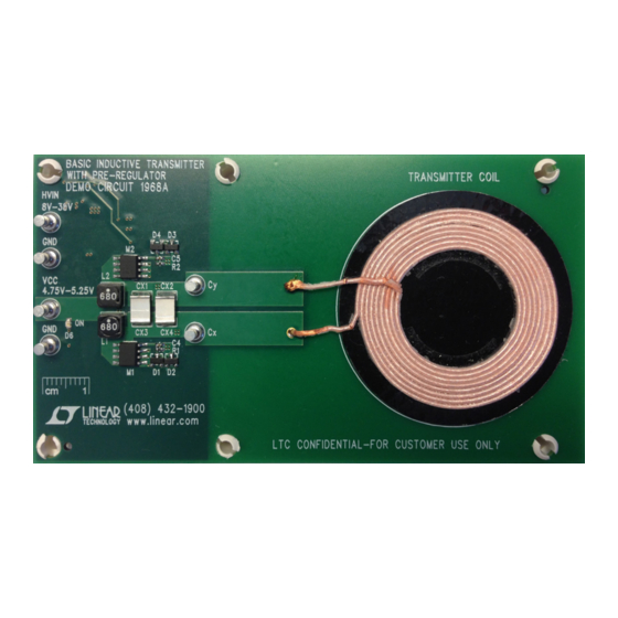
Figure 1. DC1968A Basic Transmitter Board
This datasheet has been downloaded from
DC1969A-A/DC1969A-B
LTC4120EUD-4.2/LTC4120EUD
Wireless Power Receiver and
400mA Buck Battery Charger
coils. The basic transmitter does not support foreign object
detection, i.e. coins or other metallic objects.
Design files for this circuit board are available at
http://www.linear.com/demo/DC1969A
L, LT, LTC, LTM, Linear Technology and the Linear logo are registered trademarks of Linear
Technology Corporation. All other trademarks are the property of their respective owners.
Kit Build Options
KIT NUMBER
DC1969A‑A
DC1969A‑B
Receiver Board Build Options
Rx BOARD
DC1967A‑A
DC1967A‑B
Specifications are at T
= 25°C
A
CONDITIONS
IHVIN ≤ 500mA at HVIN = 8V
IV
= 0mA to 700mA
CC
R9 = 1.40MΩ, R10 = 1.05MΩ
V
= 3.7V, DC1967A(R5) = 3.01kΩ
BAT
Figure 2. DC1967A-B LTC4120 Receiver Board
http://www.digchip.com
DEMO MANUAL
Tx BOARD
Rx BOARD
DC1968A
DC1967A‑A
DC1968A
DC1967A‑B
PART NUMBER
FUNCTION
LTC4120EUD‑4.2
Fixed 4.2V Float Voltage
LTC4120EUD
Adjustable Float Voltage
MIN
TYP
MAX
8
38
4.75
5.25
2.5
4.25
370
385
400
at this
page
UNITS
V
V
V
mA
dc1969aabfb
1
Advertisement

Subscribe to Our Youtube Channel
Related Manuals for Linear Technology DC1969A-A


Summary of Contents for Linear Technology DC1969A-A
- Page 1 2W to the receive board with up L, LT, LTC, LTM, Linear Technology and the Linear logo are registered trademarks of Linear to 10mm spacing between the transmit and the receive Technology Corporation. All other trademarks are the property of their respective owners.
-
Page 2: Theory Of Operation
DEMO MANUAL DC1969A-A/DC1969A-B DEMO BOARD PROCEDURE Refer to Figure 7 for the proper measurement equipment 4. Connect a bipolar supply (PS3) to the DC1967A demo setup and jumper settings and follow the procedure be‑ board BAT pin. Set the supply to 3.7V and turn on. - Page 3 DEMO MANUAL DC1969A-A/DC1969A-B THEORY OF OPERATION = 3.7V 100µA/DIV Cx-Cy 20V/DIV 10V/DIV Cx TO GND 20V/DIV 10V/DIV DC1969A F03 DC1969A F04 2µs/DIV 2µs/DIV Figure 3. DC1968A Basic Transmitter Figure 4. DC1967A Receiver The current fed topology makes the peak‑to‑peak voltage The waveforms in Figure 4 were captured at a transmit on the resonant tank equal to 2πV...
- Page 4 DEMO MANUAL DC1969A-A/DC1969A-B THEORY OF OPERATION and receive coils. The LTC4120 wireless power receiver distance of 8mm, to the battery. There is negligible transmit IC increases power transfer when power transfer is insuf‑ frequency ripple on V , and the voltage is well above the ficient.
- Page 5 DEMO MANUAL DC1969A-A/DC1969A-B THEORY OF OPERATION – 8V to 38V Supply – – Figure 7a. Using High Voltage Input – 5V Supply – Figure 7b. Using the V Input – 3.7V Bipolar Supply – Figure 7c. Receive Board with Battery Emulator...
- Page 6 DEMO MANUAL DC1969A-A/DC1969A-B THEORY OF OPERATION Figure 8. Measuring Input or Output Ripple CISPR 11 CLASS A LIMIT CISPR 11 CLASS B LIMIT 1968A AND 1967A-B 1968A ONLY 1968A AND 1967A-B –10 AND BATT –20 1,000 FREQUENCY (MHz) GTEM CELL MEASUREMENT...
-
Page 7: Parts List
DEMO MANUAL DC1969A-A/DC1969A-B PARTS LIST ITEM REFERENCE PART DESCRIPTION MANUFACTURER/PART NUMBER DC1967A Required Circuit Components C2S1, C2P1 CAP, CHIP, C0G, 0.0047µF, ±5%, 50V, 0805 MURATA, GRM2165C1H472JA01D C2P2 CAP, CHIP, C0G, 0.0018µF, ±5%, 50V, 0603 KEMET, C0603C182J5GAC7533 C2S2 CAP, CHIP, C0G, 0.022µF,±5%, 50V, 0805 MURATA, GRM21B5C1H223JA01L CAP, CHIP, X5R, 10µF, ±20%, 16V, 0805... - Page 8 DEMO MANUAL DC1969A-A/DC1969A-B PARTS LIST ITEM REFERENCE PART DESCRIPTION MANUFACTURER/PART NUMBER 15mm DOUBLE SIDED TAPE 3M, 34‑8705‑5578‑5 STAND‑OFF, NYLON, 0.375" KEYSTONE, 8832 DC1967A-A Required Circuit Components NO LOAD. SMD 0402 RES, CHIP, 0Ω JUMPER, 1/16W, 0402 VISHAY, CRCW04020000Z0ED 400mA Wireless Synchronous Buck Battery Charger, LINEAR TECH., LTC4120EUD‑4.2...
-
Page 9: Schematic Diagram
DEMO MANUAL DC1969A-A/DC1969A-B SCHEMATIC DIAGRAM dc1969aabfb... - Page 10 DEMO MANUAL DC1969A-A/DC1969A-B SCHEMATIC DIAGRAM dc1969aabfb...
- Page 11 Information furnished by Linear Technology Corporation is believed to be accurate and reliable. However, no responsibility is assumed for its use. Linear Technology Corporation makes no representa‑ tion that the interconnection of its circuits as described herein will not infringe on existing patent rights.
- Page 12 Linear Technology Corporation (LTC) provides the enclosed product(s) under the following AS IS conditions: This demonstration board (DEMO BOARD) kit being sold or provided by Linear Technology is intended for use for ENGINEERING DEVELOPMENT OR EVALUATION PURPOSES ONLY and is not provided by LTC for commercial use. As such, the DEMO BOARD herein may not be complete in terms of required design‑, marketing‑, and/or manufacturing‑related protective considerations, including but not limited to product safety...
Need help?
Do you have a question about the DC1969A-A and is the answer not in the manual?
Questions and answers