Table of Contents
Advertisement
Available languages
Available languages
Quick Links
Advertisement
Chapters
Table of Contents

Related Manuals for HTS ECO-IR 180A

Summary of Contents for HTS ECO-IR 180A
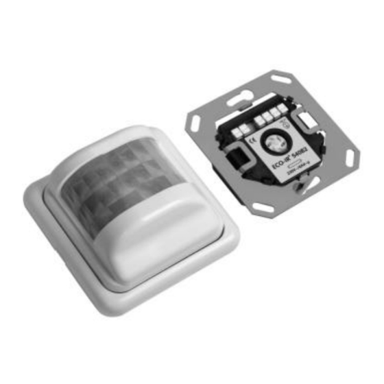
- Page 1 High Technology Systems Präsenzmelder ECO-IR 180-24V / ECO-IR 360-24V Modifikation: Nachlaufzeit «HLK» von 1 - 60Min. einstellbar Anschlussbild Rückseite Sensorteil 24V @ 230V~ 2A 230V~ 2A 24V= 2A 24V= 2A . . . B1 B2 A1 A2...
- Page 2 1 Min. – 60 Min. Artikelnummern ECO-IR 180-24V kompl. 20 180 008 ECO-IR 360-24V kompl. 20 360 027 ECO-IR 180A-HR Sensor 20 180 006 ECO-IR 360A-HR Sensor 20 360 022 ECO-IR 540Z Leistungsteil 20 540 004 ECO-IR 540Z Leistungsteil 20 540 004...
- Page 3 Produktbeschreibung ® Der ECO-IR ist ein vielseitig einsetzbarer Passiv-Infrarot Präsenzmelder. Er erfaßt die Anwesenheit von Personen und mißt das einfallende Tageslicht. ® High Technology Systems ECO-IR 180A / 360A Er besitzt zwei unabhängige Ausgänge (Relaiskontakte) zur Steuerung von Beleuchtung und Heizung, Lüftung, Klima (HLK).
-
Page 5: Table Of Contents
Die ECO-IR 180A und ECO-IR 360A müssen nach dem Einstecken des Oberteiles mit der Wir erklären, daß das CE Zeichen von HTS gemäß den Richtlinien EN 50 081-1, EN 50 082-1 und Sicherheitsverriegelung gegen unbeabsichtigtes Herausrutschen gesichert werden (Abb. 3). - Page 6 ten zu integrieren oder genügend seitlichen Abstand zu halten. Achten Sie bei abgehängten Beleuchtungskörpern auf eine mögliche Abschattung des Erfassungsbereiches.
-
Page 7: Montage Und Anschluß
Sicherheitsverriegelung links und rechts bis zum Anschlag heraus (Abb. 3). Ziehen Sie den Sensorteil (weiß) vom Leistungsteil (schwarz) ab. 4 Einsatz Anschluß ECO-IR 180A für Wandmontage Schließen Sie das Leistungsteil ECO-IR 540B2 gemäß Anschlußschema (Abb. 4, 5) an: Der Erfassungsbereich beträgt horizontal 180°, vertikal 55° - Nulleiter an N (Abb. -
Page 8: Inbetriebnahme
DE -5 DE - 6 In Korridoren kann der ECO-IR 180A auch an die Decke montiert werden. Erfassungsbereich Nachlaufzeit „Licht“ beachten oder Planungsunterlagen anfordern. • Gewünschte minimale Nachlaufzeit für den Schaltkontakt „Licht“ am Potentiome- ECO-IR 360A für Deckenmontage (z. B. Erfassung von ter „Min.Time Minutes“... - Page 9 Sehintensive Tätigkeiten (Feinmontage, Labors, Werkstätten, Zeichnungsräume Skala > 5 • Stecken Sie nach dem Einstellen das Oberteil auf das Leistungsteil. Achten Sie auf identi- etc.) sche Orientierung der Schrift: Lage der Beschriftung muß auf beiden Teilen gleich sein. Helligkeitsmessung deaktiviert (Kein Tageslichteinfluß erwünscht oder kein Skala >...
-
Page 10: Copyright
Die Mängelhaftung bezieht sich nicht auf Transportschäden, ferner nicht auf Schäden infolge erfolgt die Reaktion auf Nichtbeachtung der Bedienungsanleitung sowie nicht fachgerechter Installation. Helligkeitswechsel verzögert. Zur Behebung eines Mangels ist HTS die erforderliche Zeit und Gelegenheit zu gewähren. Licht brennt nie, 1. Luxwert zu tief. 1. Luxwert höher wählen. - Page 11 Störung Ursache Abhilfe Störung Ursache Abhilfe 2. Direkteinstrahlung von FL- 2. Punkt 2.3 beachten, Anordnung Leuchten auf Sensor zu hoch. Melder zu Leuchten überprüfen. Licht brennt dauernd / 1. Luxwert ist zu hoch. 1. Luxwert tiefer wählen. Licht brennt dauernd / 1.
- Page 12 • lorsque la mise en service se déroule comme prescrit, • l’utilisateur connaît le fonctionnement de l’appareil. Nous déclarons que le label CE est utilisé par HTS selon les directives EN 50 081-1, EN 50 082-1 EN 60 669. ATTENTION N’ouvrez pas l’appareil.
- Page 13 Lorsque la garniture d’éclairage est pendante, veillez à ce que la zone de détection ne soit Le verrouillage de sécurité doit être mis sur l’ECO-IR 180A et sur l’ECO-IR 360A afin qu’ls ne masquée en aucun endroit. tombent pas de manière inopinée.
- Page 14 à 2,2 m. point neutre sur N Dans les couloirs, l’ECO-IR 180A peut aussi être fixé au plafond. Prendre en considération le la phase sur L champ de détection ou demander la documentation de planification correspondante.
- Page 15 FR - 5 FR - 6 • Régler la valeur de commutation de la luminosité au potentiomètre «Lux». Pour le réglage de base, veuillez respecter les directives de réglage que vous trouverez dans les tableaux aux pages suivantes (voir aussi fig. 2). Les consignes ne sont que des valeurs indicatives.
- Page 16 Eblouir le détecteur de présence avec une lampe de poche entraîne l’extinction de la lumière. Il doit être garanti suffisamment de temps à HTS et lui être donné l’occasion de réparer un dé- La phase de maintenance prend fin automatiquement au bout de 10 minutes. Au valeur de faut.
- Page 17 FR - 9 FR - 10 16 Réparation des dérangement Dérangement Cause Remède : la lampe interrompue interrup- Dérangement Cause Remède : teur. La lumière s'allume une fois pendant 90 s après attendre pendant 90 s. L’appareil La lumière s’allume et 1.
- Page 18 FR - 11 Dérangement Cause Remède : 5. « effet d’apprentissage au- 4. contrôler le réglage de la valeur tomatique » 5. ôter et remettre l’ECO-IR, procé- der de nouveau à l’initialisation. La lumière s’éteint bien qu’il la temporisation d'extinction contrôler les recommandations de y ait une présence.
- Page 19 • the user is familiar with the functioning of the device. ECO-IR presence detectors may only be used indoors We hereby confirm that the CE symbol has been used by HTS in pursuant to the EN 50 081-1, (system of protection IP 40).
-
Page 20: Mounting And Connecting The Device
EN -3 EN - 4 With indirect lighting, ensure that the main part of the light from these lamps is not directed Both ECO-IR models must be mounted in housings (surface-mounted or concealed installa- at the detector as this affects the daylight measurement. tion, single housing) (Fig. -
Page 21: Applications
EN - 5 EN - 6 - Neutral to N The ECO-IR 180A can also be mounted on the ceiling in corridors. Please note the detection - Phase to L range or ask for planning documentation. - Phase connected to Aî... - Page 22 EN - 7 EN - 8 • Set the desired minimum switch-off delay time for the "Light" switching contact on Visually intensive activities scale> 5 the "Min. time minutes" potentiometer. (high-precision assembly areas, workshops, drawing rooms etc.) No daylight effects required or no daylight present. Brightness measurement is Scale >...
-
Page 23: Warranty
Submission In the event of a warranty claim, the device should be sent with the delivery certificate and a brief description of the fault to the relevant dealer or, if purchased directly, to HTS. 23 Copyright The design, hardware and software of these devices are protected by patent. -
Page 24: Troubleshooting
EN -9 EN - 10 24 Troubleshooting Fault Cause Remedy tor from fluorescent lamps too ment of detector with regard to lamps. Fault Cause Remedy high. Lighting system on after Both outputs are closed for 90 Wait for 90 s. The device then Lights on continuously / 1. -
Page 25: Technical Data (Rear Of Instruction Manual)
ECO-IR 180A complet ECO-IR 180A complete 20 180 001 l'intermédiaire de relais externes lays must be used. ECO-IR 180A capteur ECO-IR 180A sensor module 20 180 002 (ou des contacteurs ECO-IR 360A complet ECO-IR 360A complete 20 360 001 électromagnétiques). - Page 26 50V= 2A µ, 230V~ 2A µ ECO-IR 360A komplett 20 360 001 Kontaktausführung Schutzklasse II EN 60730-1 ECO-IR 360A Sensorteil 20 360 002 empfohlene Maximallast 100W / 460VA ECO-IR 540B2 Leistungsteil 20 540 006 Änderungen vorbehalten 11030 00305 05/00 © by HTS...
Need help?
Do you have a question about the ECO-IR 180A and is the answer not in the manual?
Questions and answers