Advertisement
Quick Links
Advertisement

Related Manuals for Mitsubishi Electric apricot FTs 486

Summary of Contents for Mitsubishi Electric apricot FTs 486
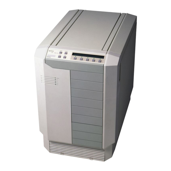
- Page 1 ADD-ON INSTALLATION GUIDE FTs 486 apricot MITSUBISHI ELECTRIC...
- Page 2 All rights reserved; no use or disclosure without written consent. Copyright © Apricot Computers Limited 1992 Published by Apricot Computers Limited 3500 Parkside Birmingham Business Park BIRMINGHAM B37 7YS MITSUBISHI ELECTRIC Printed in the United Kingdom Part no. 15033931...
-
Page 3: Table Of Contents
Contents Introduction 2 Anti-static precautions 3 Power down procedure 4 Power up procedure 5 Removing the left side panel 6 Adapter cards 7 Installing memory modules 9 CPU module upgrade 14... -
Page 4: Introduction
Introduction This guide contains instructions on installing expansion cards and extra memory in your computer. This document should be your only source of information when installing either of these. You should read this document before purchasing extra memory. If, having read the relevant instructions, you are not confident about installing the upgrade, you may wish to have your supplier or service organisation install it for you. -
Page 5: Anti-Static Precautions
Anti-static precautions All electronic components and equipments are sensitive to static electricity. Even small electrostatic discharges can render components useless or severely shorten their working life, therefore you should always take preventative measures. No work should be carried on any item unless it is in a Special Handling Area (SHA) as defined in BS CECC 00015:Part 1. -
Page 6: Power Down Procedure
Power down procedure If security is enabled a user of appropriate authority must be logged on before the system can be powered down. 1. Push the button STANDBY 2. Confirm by pushing the button under the “Y” on the LCD display. 3. -
Page 7: Power Up Procedure
Power up procedure 1. Ensure that the battery isolation switch is in the “0” position. 2. Connect the FTs to any auxiliary external battery supply. 3. Plug in the mains power supply. 4. Set the BATTERY ISOLATION SWITCH to the “1” position. -
Page 8: Removing The Left Side Panel
Removing the left side panel The left side panel (as viewed from the front) is located by two pegs at the front, and secured by two thumbscrews and a keylock at the rear. The left side panel allows access to the electronics bay where the motherboard and power distribution board are located. -
Page 9: Adapter Cards
Adapter cards Eight 32-bit Micro Channel slots are available on the system board for the installation of adapter cards. One slot is always occupied by a hard disk controller. Each slot has a blanking plate in the rear panel and a slot in the bridge assembly at the front of the system unit. - Page 10 To install an adapter card: 1. Power the system down. 2. Remove the left side panel of the system unit. 3. Loosen the thumbscrew at the bottom of the blanking plate for the slot that the adapter is to occupy, and remove the blanking plate. Note If the thumbscrew is tight it may be necessary to use a screwdriver or coin to release the...
-
Page 11: Installing Memory Modules
Installing memory modules A variety of memory configurations are possible in the Apricot FTs. Two different capacities of Single Inline Memory Modules (SIMMs) are available: 1 Mbyte and 2 Mbyte. The following diagrams show the type of SIMM that should be fitted in each slot for each possible memory capacity. - Page 12 Obtaining access The SIMM sockets are accessible with the left side panel removed. To obtain access: 1. Take suitable anti-static precautions. 2. Remove the left side panel. 3. Identify the SIMM sockets from the illustration below. SWITCHES SIMM SOCKETS...
- Page 13 Installation If you are fitting additional SIMMs remove those already installed. Removing SIMMs Starting with the SIMM nearest the front of the system unit and working towards the rear: 1. Note which socket the SIMM is in. 2. Lever the metal clips on each side of the socket gently away from the SIMM using your thumbnails.
- Page 14 Inserting SIMMs From the illustrations showing the possible SIMM combinations decide which SIMM capacity will be installed in each slot. Then, working from the socket nearest the rear of the system unit towards the front, install the SIMMs. To fit a SIMM: 1.
- Page 15 7. Rotate the SIMM into the vertical position by pushing gently on the top corners. 8. If the SIMM is properly located the SIMM should remain in position held by the securing clips, and with a small plastic lug through the holes on either side of the SIMM.
-
Page 16: Cpu Module Upgrade
CPU module upgrades The add-ons described earlier may be installed by a confident and competent user. The installation of a CPU module upgrade is more complex, and should only be carried out by competent service personnel. A range of 80486 processors are available for the system board fitted in the Apricot FTs. - Page 17 APRICOT COMPUTERS LIMITED 3500 PARKSIDE BIRMINGHAM BUSINESS PARK BIRMINGHAM B37 7YS. MITSUBISHI ELECTRIC Part No 15033931 Revision 01...
Need help?
Do you have a question about the apricot FTs 486 and is the answer not in the manual?
Questions and answers