
Subscribe to Our Youtube Channel
Related Manuals for Hafco Metalmaster DMF-44


Summary of Contents for Hafco Metalmaster DMF-44
- Page 1 OPERATION MANUAL Model. DMF-44 Order Code D185 Edition No : DMF-44-1 Date of Issue : 07/2020...
- Page 2 This manual is only for your reference. Owing to the continuous improvement of the Hafco/Metalmaster machine, changes may be made at any time without obligation or notice. Please ensure the local voltage is the same as listed on the specification plate before operating this electric machine.
-
Page 3: Table Of Contents
OPERATION MANUAL C O N T E N T S: 1. GENERAL MACHINE INFORMATION 1.1 Specifications.............. 4 1.2 Identification............... 5 1.3 Controls................. 6 2. SAFETY 2.1 General Metalworking Machine Safety..... 8 2.2 Specific Safety For Drill/Mill........11 3. POWER SUPPLY 3.1 Eletrical Requirments.......... -
Page 4: Specifications
OPERATION MANUAL 1.1 SPECIFICATION Order Code D185 MODEL DMF-44 Type Pedestal Table Size (mm) 730 x 210 Column Size (mm) Ø125 Spindle Tape Longitudinal Travel (X-Axis) (mm) Cross Travel (Y-Axis) (mm) Vertical Travel (Z-Axis) (mm) Type of Slides Dovetail Spindle to Table (mm) Spindle Travel (mm) Spindle Diameter (mm) Ø75... -
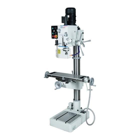
Page 5: Identification
OPERATION MANUAL 1.2 IDENTIFICATION Control Panel Longitudinal Travel Hand-wheel Head Vertical Travel Handle Motor Base Speed Selection Levers Coolant Pump Fine Spindle Feed Cross Travel Hand-wheel Course Spindle Feed Spindle Slotted Table Cutter Safety Guard... -
Page 6: Controls
OPERATION MANUAL 1.3 CONTROLS The purpose of this control overview is to provide the novice machine operator with a basic understanding of how the machine is used during operation, and the machine controls and what they do. It also helps the operator to understand if they are discussed later in this manual. NOTE: DO NOT start the machine until all of the setup instructions have been performed. - Page 7 OPERATION MANUAL 4.2 DOWN- FEED CONTROLS The machine is equipped with a course down-feed control mainly used for drilling or quick adjustment and a fine down-feed control used mainly when milling or where controlled down- feed is required. (Fig.4.3) A. Depth Stop and Scale B.
-
Page 8: Safety
OPERATION MANUAL 2. SAFETY 2.1 GENERAL METALWORKING MACHINE SAFETY DO NOT use this machine unless you have read this manual or have been instructed in the use of this machine in its safe use and operation WARNING This manual provides safety instructions on the proper setup, operation, maintenance, and service of this machine. - Page 9 OPERATION MANUAL 2.1 GENERAL METALWORKING MACHINE SAFETY Cont. Ensure that keys and adjusting wrenches have been removed from the machine before turning on the power. Appropriate storage for tooling should be provided. Ensure that all cutting tools and blades are clean and sharp. They should be able to cut freely without being forced.
- Page 10 OPERATION MANUAL 2.1 GENERAL METALWORKING MACHINE SAFETY Cont. HAZARDS ASSOCIATED WITH MACHINES include, but are not limited to: • Being struck by ejected parts of the machinery • Being struck by material ejected from the machinery • Contact or entanglement with the machinery •...
-
Page 11: Specific Safety For Drill/Mill
OPERATION MANUAL 2.2 SPECIFIC SAFETY FOR DRILL/MILL DO NOT use this machine unless you have been instructed in its safe use and operation and have read and understood this manual Safety glasses must be Long and loose hair must Gloves must not be worn at all times in work be contained. -
Page 12: Power Supply
OPERATION MANUAL 3. POWER SUPPLY 3.1 ELECTRICAL REQUIREMENTS Place the machine near an existing power source. Make sure all power cords are protected from traffic, material handling, moisture, chemicals, or other hazards. Make sure there is access to a means of disconnecting the power source. The electrical circuit must meet the requirements for 240V. -
Page 13: Setup
OPERATION MANUAL 4. SETUP 4.1 UNPACKING This machine was carefully packaged for safe transport. When unpacking, separate all enclosed items from packaging materials and inspect them for shipping damage. If items are damaged, or missing, please contact your local distributor. NOTE: Save all the packaging materials until you are completely satisfied with the machine and have resolved any issues between your distributor or the transport company. -
Page 14: Site Preparation
OPERATION MANUAL 4.4 SITE PREPARATION When selecting the site for the machine, consider the largest size of workpiece that will be processed through the machine and provide enough space around the machine for operating the machine safely. Consideration should be given to the installation of auxiliary equipment. Leave enough space around the machine to open or remove doors/covers as required for the maintenance and service as described in this manual. -
Page 15: Anchoring To The Floor
OPERATION MANUAL 4.6 ANCHORING TO THE FLOOR The machine is best mounted on a concrete slab. Masonry anchors with bolts are the best way to anchor machinery, because the anchors sit flush with the floor surface, making it easy to unbolt and move the machine later, if needed. -
Page 16: Assembly
OPERATION MANUAL 4.8 ASSEMBLY The machine must be fully assembled before it can be operated. To make sure the assembly process goes smoothly, clean all parts that have any heavy-duty rust preventative on them. Set Screw To assemble the machine: 1. -
Page 17: Checking Lubrication
OPERATION MANUAL 4.9 CHECKING LUBRICATION The headstock oil reservoir must have the proper amount of oil in it before the machine can be operated ight lass for the first time. Damage caused by running the machine without oil in the reservoir will not be covered under warranty. - Page 18 OPERATION MANUAL 4.10 TEST RUN Cont. 5. Twist EMERGENCY STOP button (G in Fig. 4.10) clockwise until it pops out - this resets the button and enables the power to control panel and motor. 6. Press the SPINDLE FORWARD button (A in Fig 4.10). Spindle should rotate clockwise (as viewed from top) and machine should run smoothly with little to no vibration or rubbing noises.
-
Page 19: Operation
OPERATION MANUAL 5. OPERATION. 5.1 OPERATION OVERVIEW The purpose of this overview is to provide the novice machine operator with a basic under- standing of how the machine is used during operation, so the machine controls/components discussed later in this manual are easier to understand. Due to the generic nature of this overview, it is not intended to be an instructional guide. -
Page 20: Headstock Movement
OPERATION MANUAL 5.2 HEADSTOCK MOVEMENT The headstock is designed to move up and down along the Z axis and tilt 90 degrees side to side. THE HEAD IS HEAVY AND WILL REQUIRE SUPPORT WHEN TILTING. ARRANGE FOR SOME HELP TO SUPPORT THE HEAD. To Tilt The Headstock To Raise or Lower the Headstock 1. -
Page 21: Spindle Movement
OPERATION MANUAL 5.3 SPINDLE MOVEMENT The machine is fitted with two options for Spindle down-feed movement on this machine It is controlled by two mechanisms: 1) The coarse down-feed lever, 2) Fine down-feed hand-wheel USING COARSE DOWN FEED Coarse down-feed is typically used for drilling, because it allows you to quickly lower the spindle with varying speed/pressure, using the handles (B in Fig. -
Page 22: Setting Up For Tapping
OPERATION MANUAL 5.4 SETTING UP FOR TAPPING The Hafco Metalmaster DMF-44 is fitted with a Tapping mode. When selected the spindle turns clockwise until it comes up against a micro switch in the depth stop which will bring the spindle to a complete stop and then reverse the spindle. The feed of the tap is by hand using the course down feed with handles. - Page 23 OPERATION MANUAL 5.5 TABLE MOVEMENT The table has travel in three directions called “X” , “Y” and “Z” axis (Fig. 5.11) X Axis is the Longitudinal Travel Y Axis is the Cross Travel Z Axis is the Vertical Travel Left to Right Movement “X” Axis In and Out Movement Longitudinal Travel “Y”...
-
Page 24: Installing And Removing The Tooling
OPERATION MANUAL 5.6 INSTALLING & REMOVING THE TOOLING The machine is fitted with a 3MT spindle to hold the tooling. While the taper will hold drills where pressure is applied to the end of the drill, with milling cutters pressure is applied to the side of the cutter , therefore the cutter arbor needs to be held also with a draw-bar. -
Page 25: Changing The Speed
OPERATION MANUAL 5.7 CHANGING THE SPEEDS Selecting the correct spindle speed is important for safe and satisfactory results, as well as maximizing tool life. To set the spindle speed for your operation, you will need to: 1. Determine the best spindle speed for the cutting task, 2. -
Page 26: Maintenance
OPERATION MANUAL 6. MAINTENANCE 6.1 LUBRICATION: All ball bearings in your mill/drill are sealed for life, requiring no lubrication. Points requiring lubrication are: 1. Internal spline drive assembly. Keep this area well lubricated with a good grade grease, insert grease in the hole at the top of spindle pulley spline driver, lube TWICE YEARLY. 2. -
Page 27: Gib Adjustment
OPERATION MANUAL 6.3 GIB ADJUSTMENT Gibs are tapered lengths of metal that are sandwiched between two moving surfaces. Table Gib Gibs the gap between these surfaces and how they slide past one another. Correctly adjusting the gibs is critical to producing good milling results. -
Page 28: Troubleshooting
OPERATION MANUAL 6.4 TROUBLESHOOTING Symptom Possible Cause Possible Solution 1. Power not connected to the machine 1. Check that power is connected to the machine Machine will not 2. Emergency Stop Button not reset 2. Reset emergency stop button start 3. -
Page 29: Spare Parts
OPERATION MANUAL SPARE PARTS SECTION Model. DMF-44 Order Code D185 Edition No : DMF-44-1 Date of Issue : 07/2020 The following section covers the spare parts diagrams and lists that were current at the time this manual was originally printed. Due to continuous improvements of the machine, changes may be made at any time without notification. - Page 30 OPERATION MANUAL 240V WIRING DIAGRAM...
- Page 31 OPERATION MANUAL DMF-44 HEAD SPARE PARTS DIAGRAM NOTE: SOME INDIVIDUAL PARTS MAY ONLY BE AVAILABLE AS AN ASSEMBLY...
- Page 32 OPERATION MANUAL DMF-44 HEAD SPARE PARTS LIST ITEM DESCRIPTION QTY. ITEM DESCRIPTION QTY. 20010B HEAD BODY 6X14 20011B HEAD BODY COVER 6X28 Ø 62 INT RETAINING RING Ø 8 BALL Ø 35 INT RETAINING RING SPRING 20018B AIRTIGHT BASE Ø18 EXT RETAINING RING 45X35X10 AIRTIGHT RING 5X50...
- Page 33 OPERATION MANUAL DMF-44 HEAD SPARE PARTS LIST ITEM DESCRIPTION QTY. ITEM DESCRIPTION QTY. 20024B SEPARATING RING ADJUST HANDLE 20133B BEARING COVER 20125B LEVER SHAFT M5X6 SCREW (R8) 20022-1B LEVER M5X4 PIN (R8) 20204-2B LEVER BRACKET 20015 WORM WHEEL BOX EXT RETAINING RING 20119 WORM SHAFT M6X16 SCREW...
- Page 34 OPERATION MANUAL DMF-44 TABLE & COLUMN SPARE PARTS DIAGRAM NOTE: SOME INDIVIDUAL PARTS MAY ONLY BE AVAILABLE AS AN ASSEMBLY...
- Page 35 OPERATION MANUAL DMF-44 TABLE & COLUMN SPARE PARTS LIST ITEM DESCRIPTION QTY. ITEM DESCRIPTION QTY. 10002/40H BASE SCREW M10 X 40 10001/40H COLUMN 10023/40H HANDLE 10003/40H LIFTING TABLE 10022/40H ADJUST BOLT 10005/40H SLIP SADDLE WASHER 12 10004/40H WORK TABLE BOLT M16 X 190 10016/40H ELEVATING BODY NUT M16 10014/40...
-
Page 36: Risk Assessment Sheets
General Machinery Safety Instructions Machinery House requires you to read this entire Manual before using this machine. 1. Read the entire Manual before starting 14. Use correct amperage extension cords. machinery. Machinery may cause serious injury if Undersized extension cords overheat and lose not correctly used. - Page 37 Milling Machine Safety Instructions Machinery House requires you to read this entire Manual before using this machine. 1. Maintenance. 9. Reversing the spindle. Make sure the mill is turned off and Make sure the spindle disconnect from the main power supply and make has come to a complete stop before changing the sure all moving parts have come to a complete stop direction of the spindle.
Need help?
Do you have a question about the Metalmaster DMF-44 and is the answer not in the manual?
Questions and answers