Advertisement
Available languages
Available languages
Quick Links
INSTRUCTIONS FOR USE, NÁVOD K POUŽITÍ
MOTOR DRIVE
MOTOROVÝ POHON
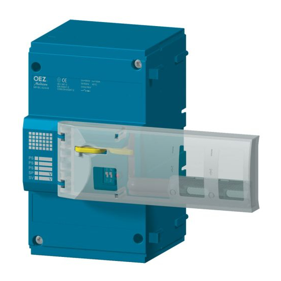
1
Installation, service and maintenance of the electrical equipment may be carried out by an authorized
person only.
Montáž, obsluhu a údržbu smí provád t jen osoba s odpovídající elektrotechnickou kvalifikací.
MP-BC-X...-B
ENGLISH
ESKY
991150f
Z00
Advertisement

Subscribe to Our Youtube Channel
Related Manuals for OEZ MP-BC-X B Series


Summary of Contents for OEZ MP-BC-X B Series
- Page 1 ENGLISH ESKY INSTRUCTIONS FOR USE, NÁVOD K POUŽITÍ MOTOR DRIVE MOTOROVÝ POHON MP-BC-X...-B Installation, service and maintenance of the electrical equipment may be carried out by an authorized person only. Montáž, obsluhu a údržbu smí provád t jen osoba s odpovídající elektrotechnickou kvalifikací. 991150f...
- Page 2 Control basic description Základní popis pohonu Rated data Jmenovité údaje Locking by (three) padlocks Uzamykání (t emi) visacími zámky Accessories of circuit breaker description Popis príslušenství jisti e Circuit breaker control lever drive dog Unaše ovládací páky jisti e Tilted protective cover Odklopený...
- Page 3 Tilted protective cover Odklopení bezpe nostního krytu Circuit breaker preparation íprava jisti e - 3 - 991150f...
- Page 4 Conductor flexible Conductor flexible Ohebný vodi Order no.69008-0724 www.molex.com Official electronic, s.r.o. Zlin +420 577 525260-1 Nebo Conductor flexible onductor f lexible Ohebný vodi . OD - BC - KA02 - 4 - 991150f...
- Page 5 Drive preparation for use with DIN rail íprava pohonu pro použití s DIN lištou Mounting Montáž - 5 - 991150f...
- Page 6 A - A Attention! Terminal cover is used as a fixing element fastening the drive to the circuit breaker, and the circuit breaker must always be equipped with it. Pozor! Kryt svorek slouží jako fixa ní prvek upev ující pohon k jisti i a jisti jim musí...
- Page 7 Drive fastening by means of DIN rail Upevn ní pohonu pomocí DIN lišty Attention! To enable easy dismantling of the motor drive from a number of devices, it is recommended to leave a distance of at least 2 mm from the other devices. Pozor! Pro možnost snadné...
- Page 8 Motor drive automatic mode presetting edvolby automatického provozu motorového pohonu Mode 1 Režim 1 Mode 2 Režim 2 Mode 3 Režim 3 Circuit breaker Automatic Circuit breaker Circuit breaker Switch Preset switching on to mode switching off loading to Mode position description position...
- Page 9 Poloha edvolba Popis Vypnutí jisti e Natažení jisti e Zapnutí jisti e Režim epína- automatického do polohy edvolby do polohy do polohy provozu Automatické Auto - Nadproudovou Motorový pohon Stisknutí tla ítka natažení je 1 *) spouští provede automaticky zapnuté - Revizním tla ítkem Auto...
- Page 10 Click Attention! With safety cover lifted off the motor drive is disconnected from supply voltage. Pozor! i odklopeném bezpe nostním krytu je motorový pohon odpojen od napájecího nap tí. Putting into service Uvedení do provozu Attention! Supply connector must not interfere in de-ionization spaces of the other devices. Pozor! Napájecí...
- Page 11 Locking Uzamykání In use of one or two padlocks one of the padlocks must be preferably placed in this part of the opening in the lockable bar. i použití jednoho, nebo dvou visacích zámk , musí být jeden ze zámk ednostn umíst n do této ásti otvoru v uzamykací...
- Page 12 Cover sealing Zaplombování krytu Drive manual control Ru ní ovládání pohonu - 12 - 991150f...
- Page 13 - 13 - 991150f...
- Page 14 Wiring diagram Schéma zapojení Motor drive control circuit Ovládací obvod motorového pohonu Motor drive Motorový pohon HL 1 HL 2 HL 3 HL 4 Motor drive control circuit, signalling Ovládací obvod motorového pohonu, signalizace - 14 - 991150f...
- Page 15 Diagram description motor drive MP-BC... motor gear unit connector for connection of control and signalling circuits recommended wiring of the control circuits - not included of MP-BC... switch on button switch off button motor drive circuit breaker remote failure signalling (unreliable switching on/off), max.
- Page 16 0 1 1 1 1 1 1 or ERROR K1 K2 K3 K4=HL. Example of use: ever is in position ... K1=1 (for HL1 and HL3) DIP switch is set to ON ... K2=1 (for HL2, HL3 and HL4 ) Safety cover is lifted off ...
- Page 17 Circuit breaker BC160 with motor drive Jisti BC160 s motorovým pohonem Circuit breaker switching off by motor Circuit breaker switching on by motor drive drive electrically using OFF push-button electrically by ON push button Vypnutí jisti e motorovým pohonem Zapnutí jisti e motorovým pohonem elektricky tla ítkem OFF elektricky tla ítkem ON Automatic operation no.
- Page 18 Circuit breaker switching off by overcurrent release or inspection push-button Vypnutí jisti e nadproudovou spouští nebo revizním tla ítkem Automatic operation no. 1 Automatic operation no. 2 and no. 3 Automatický provoz . 1 Automatický provoz . 2 a . 3 Main contacts Main contacts Hlavní...
- Page 19 Automatic operation no. 2 Automatický provoz . 2 >500 >20 60 - 60 - IMP ON IMP OFF t [ms] Automatic operation no. 3 Automatický provoz . 3 60 - 500 IMP ON t [ms] If the circuit breaker was switched off by an over current release, it is necessary to remove the cause of the failure before switching the circuit breaker on.
- Page 20 Recommended control pulses for circuit breaker switching on by motor drive after switching off by shunt trip or undervoltage release Doporu ené ovládací impulzy pro zapnutí jisti e motorovým pohonem po vypnutí nap ovou nebo podp ovou spouští Automatic operation no. 1 Automatický...
- Page 21 Automatic operation no. 3 Automatický provoz . 3 >500 60 - 500 IMP ON >200 *) >200 *) t [ms] Restart is only possible after deactivation of shunt trip or undervoltage release. *) Op tné zapnutí je možné až po deaktivaci nap ové spoušt nebo podp ové spoušt . Description of graphs Popis graf Main contacts...
- Page 22 Dimensional drawing Rozm rový ná rt 97,5 32,8 94,4 32,8 39,2 - 22 - 991150f Z00...
- Page 23 203,7 39,2 94,4 39,2 - 23 - 991150f Z00...
- Page 24 Signalling LED to indicate failure LED signalizující poruchu Possible causes of LED lighting - soft power supply - wrongly fitted drive on the circuit breaker - device failure If LED lighting is caused by other cause than a device failure, for instance by momentary drop of supply voltage during switching, the function of the motor drive can be renewed by one of the following options - short-time drop of supply voltage for approx.
- Page 25 Drilling diagram Vrtací plán 32,5 991150f...
- Page 26 ESPAÑOL SLOVENSKY PO POLSKU DEUTSCH MP-BC-... - 1 - 991150f Z00...
- Page 27 Návod k použitiu SLOVENSKY Motorový pohon - MP-BC-... Montáž, obsluhu a údržbu môže vykonáva iba osoba s odpovedajúcou elektrotechnickou kvalifikáciou. Základný popis pohonu Menovité údaje Uzamykanie (troma) vysiacími zámkami Popis príslušenstvá isti a Unáša ovládací páky isti a Odklopený bezpe nostný kryt Prepína predvo by automatickej prevádzky LED signalizujúci poruchu ( nedokon enie operácie zapnutia, vypnutia, natiahnutia )
- Page 28 Sú asné natiahnutie a zapnutie Nadprúdovou spúš ou Revíznym tla idlom Pomocnou spúš ou TEST tla ítkom Motorový pohon vykoná automaticky Obsluha musí stla tla idlo OFF Stla enie tla idla ON Stla enie tla idla ON Stla enie tla idla ON motorový pohon isti a natiahne a zapne Motorový...
- Page 29 1) Napätie na svorkách 5, 6, 9, 10 je rovnaké ako Un motorového pohonu. Pozor! Pohon demontova len pri vypnutom isti i! Príklad použitia : Poloha páky je v polohe I K1=1 ( pre HL1 a HL3 ) DIP prepína je nastavený do polohy ON K2=1 ( pre ) Bezpe nostný...
- Page 30 *) Ak isti vypla nadprúdová spúš , je nutné pred zapnutím isti a prí inu poruchy odstráni . Vypnutie isti a napä ovou spúš ou, podpä ovou spúš ou alebo tla idlom TEST Automatická prevádzka . 1 Automatická prevádzka . 2 a . 3 Hlavné...
- Page 31 - MP-BC-... (LED), "U" "U" - 6 - 991150f Z00...
- Page 32 TEST MP-BC ... - 7 - 991150f Z00...
- Page 33 10 W 1) " " 10 W 1) 10 W 1) 10 W 1) 5, 6, 9, 10 K1=1 ( HL3 ) K2=1 ( HL2, HL3 HL4 ) K3=1 ( HL3 ) K4=1 ( HL1, HL2 HL3 ) K1xK2xK3xK4=1 BC160 1,2,3 - 8 - 991150f Z00...
- Page 34 TEST IMP ON IMP OFF TEST REVIZE (LED), - 9 - 991150f Z00...
- Page 35 10 s ROHS. - 10 - 991150f Z00...
-
Page 36: Instrukcja Obs Ugi
Instrukcja obs ugi PO POLSKU Nap d silnikowy - MP-BC-... Monta , obs ug i konserwacj wykonywa mo e wy cznie odpowiednio wykwalifikowana osoby z bran y elektrotechnicznej. Opis sterowania Warto ci znamionowe Zamykanie na k udk Opis qakcesoriów wy cznika Przesuwacz d wigni steruj cej wy cznika Ods oni ta os ona bezpiecze stwa Prze cznik preselekcji aksploatacji automatycznej... - Page 37 Jednoczesne napinanie i w czenie Wyzwalaczem nadpr dowym Przyciskiem rewizyjnym Przez wyzwalacz pomocniczy Przez przycisk TEST Nap d silnikowy wykona automatycznie Obs uga powinna nacisn przycisk OFF Naci ni cie przycisku ON Naci ni cie przycisku ON Naci ni ciem przycisku ON nap d silnikowy napnie i w czy wy cznik Nap d silnikowy nie dzia a, zapali si czerwone wiat o LED.
- Page 38 HL4 Sygnalizacja wysuni cia zamykanej listwy nap du maks. dopuszczalne obci enie 10 W 1) 1) Napi cie na zaciskach 5, 6, 9, 10 jest identyczne z Un nap du silnikowego. Uwaga! Demonta tylko przy wy aczenym wy aczniku! Przyk ad zastosowania : enie d wigni w pozycji I K1=1 ( dla HL1 a HL3 ) prze cznik DIP ustawiony jest w pozycji ON...
- Page 39 Eksploatacja automatyczna nr. 3 *) Je eli wy cznik wy czony zosta przez wyzwalacz nadpr dowy, konieczne jest przed czeniem wy cznika usun przyczyn awarii. Wy czenie wy cznika wyzwalaczem napi ciowym, wyzwalaczem podnapi ciowym lub przyciskiem TEST Eksploatacja automatyczna nr. 1 Eksploatacja automatyczna nr.
- Page 40 Gebrauchsanweisung DEUTSCH Motorantrieb - MP-BC-... Die Montage, die Bedienung und Instandhaltung kann nur der Arbeiter mit der entsprechenden elektrotechnischen Qualifikation verrichten. Grundbeschreibung des Antriebes Nenndaten Verriegelung durch (drei) Vorhängeschlösser Beschriftung des Zubehörs des Leistungsschalters Mitnehmer des Betätigungshebels vom Leistungsschalter Hochgeklappte Schutzverkleidung Wahlschalter für den automatischen Betrieb LED für die Störungsanzeige ( Ein-, Ausschalten, Aufziehen wurde nicht beendigt )
- Page 41 Gleichzeitiges Aufziehen sowie Einschalten Durch Überstromauslöser Durch Revisionstaste Durch Hilfauslöser Durch TEST Taste Motorantrieb führt automatisch durch Bedienungspersonal muss die Taste drücken OFF Taste ON drücken Taste ON drücken Durch das Drücken der ON Taste wird der Leistungsschalter durch den Motorantrieb aufgezogen und eingeschaltet Motorantrieb ist außer Betrieb, rote LED leuchtet auf In diesem Regime kann der Antrieb mittels Signale ON und OFF nicht ferngesteuert werden.
- Page 42 zulässige Belastung max. 10 W 1) HL3 Signalisierung für das Öffnen der Motor-Schutzverkleidung zulässige Belastung max. 10 W 1) HL4 Signalisierung des Ausfahrens der Verschließleiste des Antriebs zulässige Belastung max. 10 W 1) 1) Klemmenspannung an den Klemmen 5, 6, 9, 10 ist gleich, wie Un des Motorantriebs Achtung! Den Antrieb nur bei dem ausgeschalteten Leistungsschalter zu demontieren! Anwendungsbeispiel :...
- Page 43 Automatische Betriebsart Nr. 2 Automatische Betriebsart Nr. 3 *) Wenn der Leistungsschalter durch Überstromauslöser ausgeschaltet wurde, muss vor dem Einschalten des Leistungsschalters die Störungsursache behoben werden Ausschalten durch Spannungsauslöser, Unterspannungsauslöser oder TEST Taste Automatische Betriebsart Nr. 1 Automatische Betriebsart Nr. 2 und Nr. 3 Hauptkontakte Hilfsschalter Schaltkontakt...
-
Page 44: Instrucciones De Uso
Instrucciones de uso ESPAÑOL Accionamiento por motor - MP-BC-... El montaje, servicio y mantenimiento puede realizar únicamente la persona con la cualificación electrotécnica correspondiente. Descripción básica del accionamiento Datos nominales Cierre con (tres) candados Descripción de accesorios del disyuntor Arrastrador (conductor) de la palanca de mando del interruptor de protección Cubierta de seguridad abierta Permutador de la preselección del servicio automático LED que señaliza la avería... - Page 45 Tender y conectar a la vez Por el disparador de sobreintensidad Por el botón de revisión Por el auxiliar de disparo Por el TEST pulsador El accionamiento por motor realizará automáticamente El operador debe pulsar el botón OFF Pulsar el botón ON Pulsar el botón ON Pulsando el botón ON, el accionamiento por motor hace tender y acciona el interruptor de protección...
- Page 46 carga máx. permitida 10 W 1) HL2 Señalización de la posición de la palanca del interruptor de protección "tendido" carga máx. permitida 10 W 1) HL3 Señalización de la apertura de la cubierta de protección frontal del accionamiento carga máx. permitida 10 W 1) HL4 Señalización del desencajamiento de la regleta de encierre del accionamiento carga máx.
- Page 47 Los impulsos de mando recomendados para conexión del interruptor de protección mediante el accionamiento por motor, después de la desconexión por el disparador de sobreintensidad, u el botón de revisión Funcionamiento automático No. 1 Funcionamiento automático No. 2 Funcionamiento automático No. 3 *) Si es que el interruptor de protección fue desconectado por el disparador de sobreintensidad, antes de conectar el interruptor hay que eliminar el motivo de la avería.
- Page 48 - Levantamiento de la cubierta de protección y nuevamente su cierre - Inducción del pulso a la entrada ON u OFF En el producto están usados los materiales que tienen incidencia negativa baja al medio ambiente, que no incluyen las materias peligrosas prohibidas según ROHS. - 23 - 991150f Z00...
- Page 49 - 24 - 991150f Z00...
Need help?
Do you have a question about the MP-BC-X B Series and is the answer not in the manual?
Questions and answers