Advertisement
Quick Links
Advertisement

Subscribe to Our Youtube Channel
Summary of Contents for Active Intent S001S
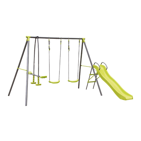
- Page 1 4-IN-1 SWING SET Owner’s Manual Model: S001S Read all instructions carefully before using this product. Retain this owner’s manual for future IMPORTANT: reference. The specification of this product may vary from this photo, subject to change without notice.
- Page 2 Table of Contents SAFETY INSTRUCTIONS ----------------------------------------------------------------------------------------- 2 CARE & MAINTENANCE INSTRUCTION -------------------------------------------------------------- 4 PARTS LIST ----------------------------------------------------------------------------------------------------------- 6 ASSEMBLY INSTRUCTIONS-------------------------------------------------------------------------------------- 10 Customer service number: 0800 422 274 MON – FRI: 8AM – 5PM SAT – SUN: 9AM – 4PM Marketed By: The Warehouse LTD 26 The Warehouse Way, Northcote, Auckland...
-
Page 3: Safety Instructions
Safety Instructions Warning: - This swing set is for family domestic use only. - This swing set is designed for use by children 3-8 years of age weighing no more than 45kgs. - This swing set has a maximum weight limit of 500lbs. - This swing set is for outdoor use only. - Page 4 equipment). Instruct children not to use the equipment in any manner other than intended. Teach children to sit in the centre of the swing play items, with their full weight in the centre of the seats. Do not allow children to stand on the seats. One child per seat only! Do not allow children to lean to the side when riding on other rides, structural members or collide with other playmates.
-
Page 5: Care & Maintenance Instruction
CARE & MAINTENANCE INSTRUCTION It is important to perform the following maintenance inspections at the beginning of each season and twice monthly thereafter. Inspect all nuts and bolts for tightness and tighten as required. It is particularly important that this procedure be followed at the beginning of each season. - Page 6 IMPORTANT CONSUMER INFORMATION SHEET The Consumer Product Safety Commission estimates that about 200,000 injuries occurred from falls from playground equipment; which requires hospital emergency treatment. Injuries from falling tend to be the most serious of all playground injury, and it may be potentially fatal; especially when it is a head injury. The ground surface under the playground equipment can be an important factor in determining the injury causing potential of a fall.
-
Page 7: Parts List
PARTS LIST Please prepare the following tools prior to assembling this equipment: Hammer Tape Measure (If you intend to install Not included Anchor, this is needed.) Flat Head and Philips Wrench Head Screwdriver (included) Not included Allen Wrench (included) Parts list for main frame assembly LEF TOP BAR 1 PC LONG TOP BAR... - Page 8 CROSS BAR 1 PC Hardware used for main frame assembly BOLT 5/16”*63 14 PCS BOLT 5/16”*63 4 PCS NYLON NUT 5/16” 18 PCS PLASTIC CAP 18 PCS ARC WASHER 32PCS SPRING WASHER 4 PCS Parts list for swing seat PVC COVERED 4 PCS CHAIN(PREASSEMBLED) EYE BOLT WITH ATTACHMENT...
- Page 9 2PCS TUBE CAP (PREASSEMBLED) SMALL NYLON BEARING 2PCS (PREASSEMBLED) LARGE NYLON BEARING 4PCS (PREASSEMBLED) 2PCS GLIDE SEAT 2PCS FOOTREST Bracket used for glide ride assembly BRACKET 1 PC BRACKET CLAMP 1 PC WASHER 4 PCS BOLT 5/16”*25 2 PCS NYLON NUT 5/16” 2 PCS PLASTIC CAP 2 PCS...
- Page 10 SLIDE SUPPORT 1 PC SLIDE LEG TUBE 2 PCS SLIDE TOP SUPPORT BAR 1 PC SLIDE FRONT SUPPORT 1 PC SLIDE LADDER STEPS 2 PCS SLIDE 1 PC Hardware used for slide assembly PLASTIC CONNECTOR 2 PCS BOLT1/4”*35 6 PCS BOLT1/4”*60 2 PCS BOLT1/4”*100...
-
Page 11: Assembly Instructions
Assembly instruction Place the playground equipment on level ground, not less than 6 ft (1.8 m) from any structure or obstruction such as a fence, garage, house, overhanging branches, laundry lines, or electrical wires. Do not install the playground equipment over concrete, asphalt, packed earth, or any other hard surface. - Page 12 Step 1 Insert A1 into the other end of A2, secure with B1, B5, B4 and B3. HINT: Please make sure that concave hole faces down.
- Page 13 Step 2 Insert small end of A4 into the socket at the end of A1.align holes on them. Secure with B1, B5, B4 and B3. Then attach the other two pieces of A4 on the other side to A2 the same.
- Page 14 Step 3 Secure with B1, B5, B4, and B3. Secure with B2, B6, B4, and B3. Insert A5, into A4, align holes on them. Attach A6 to A5. Repeat above to assemble the other A7 to A5 that is attached to the end of A2.
- Page 15 Step 4 Insert J3 into holes on A1, A2. Secure it with J8, J9, and J6 Step 5 J4 and K1 are PRE-ASSEMBLED, if you find it loosely, please follow below step Attach K1 to J4. ...
- Page 16 Step 6 Attach L5, L4 and L6 to A2 as Shown. Use special socket wrench and screw- driver to tighten the N3 and N8. Step 7 Attach M5 to L1. Secure N5, N13. M1, M2 and L1 are PRE-ASSEMBLED, if you find it loosely, please follow below step. ...
- Page 17 Step 8 Attach L1 to L5, secure with N2, and N11. Step 9 Insert 2xM3 into L2, then attach L3 to L2 with N6, lightly secure N6 with N9. Do not tighten completely. Attach the other L1, L2 and L3 by the as way as described above, once this is done, go back and securely tighten all N9.
- Page 18 Step10 Attach M4 to L2 Secure using N1 ,N9, N7 and N11 Step 11 Attach X5 to Y2 Secure using Z7 and Z1 Attach X4 to Y2 NOTE: Make sure that the bolt holes face up...
- Page 19 Step 12 Attach X6 to X1 and X2 Secure each side using Z1, Z4 and Z5 Attach X3 to X1 and X2 Align holes and hold in position Step 13 Insert the end of X4 into X1; secure using Z2, Z4 and Z5. ...
- Page 20 Step 14 Attach Y1 to X1 and A7, secure using Z3, Z7 and Z4, Z5. Step 15 Go back to secure Z3 and Z5 to X1, now. Tighten all screws.
- Page 21 You have finished assembling your playground equipment. Now go back and securely tighten all bolts and nuts before using the playground equipment. NOTE: Make sure to go back to check all hardware and securely tighten all bolts and nuts before using the playground equipment. ...
- Page 22 and create a cylindrical hole, you should use shovel to crave out the lower part of the hole, to create a large diameter hole bottom Place 2 inches brick or gravel bed as shown in drawing below Use about 45lb of concrete per leg ...
Need help?
Do you have a question about the S001S and is the answer not in the manual?
Questions and answers