
Subscribe to Our Youtube Channel
Related Manuals for KBR multisys D2-MSMT-1

Summary of Contents for KBR multisys D2-MSMT-1
- Page 1 User manual Technical parameters multisys D2-MSMT-1 Gateway from Modbus TCP to Modbus RTU, serial RS485 Your partner for System English network analysis...
- Page 2 KBR Kompensationsanlagenbau GmbH does not accept any liability for any loss or damage resulting from printing errors in or changes to this manual. In addition, KBR Kompensationsanlagenbau GmbH does not accept any liability for any loss or damage caused by defective devices or devices manipulated by the user.
-
Page 3: Table Of Contents
Explanation of safety relevant symbols ............5 Safety notes ........................ 6 Product liability ......................7 Disposal ........................7 Overvoltage and lightning protection ............. 7 multisys D2-MSMT-1 ....................8 Interface Modbus RTU serial RS-485 ..............9 Configuration via the Ethernet interface (Telnet) ..............10 2.21 Procedure for IP address 192.168.0.1 or unknown IP ........10... -
Page 4: Introduction
User manual This user manual describes the multisys D2-MSMT-1 device version. This user manual must be accessible to the user at all times (e.g. in the switch- gear cabinet). -
Page 5: Explanation Of Safety Relevant Symbols
multisys D2-MSMT Introduction Explanation of safety relevant symbols These operating instructions contain notes that must be observed for your personal safety and to avoid damage to equipment. These notes are identified by a warning sign or information symbol, depending on the degree of hazard they represent. -
Page 6: Safety Notes
multisys D2-MSMT Introduction Safety notes In order to prevent operating errors, device operation is kept as simple as possible. This will enable you to start your device up quickly. In your own interest, however, the following safety notes should be read care- fully. -
Page 7: Product Liability
Each device is subject to long-term testing before it is delivered. For details on product liability, please refer to our general terms and conditions for electronic equipment, which you can find at www.kbr.de. The warranty on device properties applies only if the device has been operated... -
Page 8: Multisys D2-Msmt-1
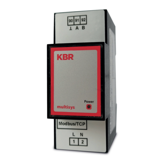
D2-MSMT multisys D2-MSMT multisys D2-MSMT-1 The multisys D2-MSMT-1 serially connects the Modbus (Modbus RTU) to the computer via an Ethernet connection (Modbus TCP). On the Modbus RTU side, it acts as master, and on the Ethernet side, it acts as slave. -
Page 9: Interface Modbus Rtu Serial Rs-485
RS-485 for the Modbus unit (3-pole multi-pin connector, 3.5 mm) Terminal no. 90 = Ground, 91 = A, 92 = B (in accordance with KBR nomenclature) DIP switch for terminating RS-485: DIP1 and DIP2 ON, DIP3 OFF = failsafe activated... -
Page 10: Configuration Via The Ethernet Interface (Telnet)
Configuration via Ethernet interface 2.2 Configuration via the Ethernet interface (Telnet) The Ethernet interface of the multisys D2-MSMT-1 can be set up using the Ethernet interface via Telnet and the Lantronix DeviceInstaller tool. Note On delivery, the devices are assigned to the IP address 192.168.0.1. - Page 11 Configuration via Ethernet interface multisys D2-MSMT Example: Modbus/TCP to RTU Bridge MAC address 0080A3A77528 Software version V3.3.0.5 (140827) XPTE Press Enter for Setup Mode Model: Device Server Plus+! (Firmware Code:YM) Modbus/TCP to RTU Bridge Setup Network/IP Settings: IP Address ..........192.168.0.1 Default Gateway .........
-
Page 12: Connection Diagram
multisys D2-MSMT Connection diagram 2.2.3 Connection diagram zu weiteren Modbusteilnehmer bzw. Leitungsabschluss to other modbus devices 90 91 92 and line termination multisys D2-MSMT-1 V1.00... -
Page 13: Technical Data
Technical data multisys D2-MSMT Technical data Power supply Power supply 85 - 265V AC/DC ; <10VA Electrical connection Connection elements Plug terminals Permissible cross section Power supply 2.5 mm of the connection lines bus connection 1.5 mm Input Fusing max. control voltage LAN connection 8P8C modular connector (RJ 45) -
Page 14: Standards And Miscellaneous
multisys D2-MSMT Technical data Standards and miscellaneous Ambient conditions Standards DIN EN 60721-3-3/A2: 1997-07; 3K5+3Z11; (IEC721-3-3; 3K5+3Z11) Operating - 5°C ….+60°C temperature Humidity 5% …..95%, non-condensing Storage -25°C ….+70°C temperature Electrical safety Standards DIN EN 61010-1: 2011-07; Protection class Overvoltage category Protection type IP20 in accordance with DIN EN 40050... - Page 15 Notes multisys D2-MSMT V1.00...
- Page 16 KBR Kompensationsanlagenbau GmbH www.kbr.de Am Kiefernschlag 7 T +49 (0) 9122 6373 - 0 D-91126 Schwabach, F +49 (0) 9122 6373 - 83 Germany E info@kbr.de...
Need help?
Do you have a question about the multisys D2-MSMT-1 and is the answer not in the manual?
Questions and answers