
Related Manuals for Eagle Eye Power Solutions BQMS


Summary of Contents for Eagle Eye Power Solutions BQMS
- Page 1 Eagle Eye Power Solutions, LLC BQMS Battery Monitoring System Installation Manual 052319 www.eepowersolutions.com | Tel: 1-877-805-3377 | Fax: 1-414-962-3660 | info@eepowersolutions.com...
-
Page 2: Table Of Contents
Table of Contents 1. Introduction ...................... 4 1.1 Safety Information ......................4 2. Product Overview .................... 5 2.1 System Composition ....................... 6 2.2 Communication Control Module (CCU) ................. 7 2.3 Measuring Unit Module ....................8 2.4 Technical Specifications ....................9 3. - Page 3 5.7.3 Connect Total Voltage & DC Power Cables to Battery System ........ 35 5.8 Install DC-CT Clamp ...................... 37 5.8.1 Connect CT Cable Harness to BQMS CCU .............. 37 5.8.2 Connect CT Cable to CT ................... 38 5.8.3 Attach CT to Battery System ..................38 5.9 Ambient Temperature Connection ................
-
Page 4: Introduction
Operation methods and safety measures described in this manual are only applicable to the defined purpose and functionality of the BQMS. If the BQMS is used in a way not specified in this manual, the safety of the equipment, personnel, and property cannot be assured. -
Page 5: Product Overview
BQMS Installation Manual 052319 2. Product Overview The BQMS is designed to monitor and analyze the state of health of stationary backup power systems by measuring and recording: string voltage, string current, cell/unit voltage, internal/connection resistance, cell/unit temperature, & ambient temperature. -
Page 6: System Composition
052319 2.1 System Composition The BQMS system composition is as follows: 1. A single Communication Control Unit (CCU) connects to a single battery bank. 2. Each bank has Modules which connect from the CCU to the battery cells in daisy chain. -
Page 7: Communication Control Module (Ccu)
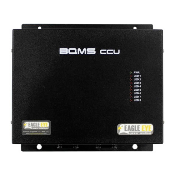
BQMS Installation Manual 052319 2.2 Communication Control Module (CCU) The CCU receives battery data and communicates with the Server. It does not store battery data, all measurement data is stored on the server. Item Description Power input termination ① POWER Power LED and alarm LED ②... -
Page 8: Measuring Unit Module
BQMS Installation Manual 052319 2.3 Measuring Unit Module The Measuring Unit (Module) relays connection between the CCU and battery cells. Each module is powered by DC from the connected battery. There are different modules for cell/unit voltages in the range of: 2V, 4V, & 12V. Modules are numbered and set at the factory prior to shipment. -
Page 9: Technical Specifications
BQMS Installation Manual 052319 2.4 Technical Specifications Applications Flooded, Sealed, & NiCad* battery types Cell/Unit Voltage Range 2V, 4V, 6V, or 12V nominal Discharge / Charge Current ±4,000A DC Voltage ±576 VDC DC Voltage / Current: ±0.5% / ±2% Cell Voltage: ±0.5% Accuracy Internal Resistance: ±2%... -
Page 10: Parts List
BQMS Installation Manual 052319 3. Parts List The following parts come standard with each BQMS package. Refer to the included packing slip for exact quantities of each part. Part Name & Purpose Picture CCU (Communication Control Unit) Main processing unit for BQMS system. - Page 11 DC voltage input CCU-Module CAN Cable (4-pin) Data communication between CCU and Modules. CCU-CCU CAN Cable (4-pin) Data communication between Modules. CT Cable Harness (3P) For connection between CT & BQMS CCU Temperature Cable Harness (8-pin) Measures temperature of battery posts...
-
Page 12: Installation Tools
BQMS Installation Manual 052319 Voltage Sensing Cable Harness (5-pin) Measures DC voltage (Vs) Current Sensing Cable Harness (3-pin) Measures resistance (Is) Provides DC power to Module 4. Installation Tools 4.1 Standard Installation Tools Tool Name & Purpose Picture Multi-meter Verification of connection voltage &... -
Page 13: Recommended Tools
Adjustment of cable length, 12 to 22AWG required Shop Snips Adjustment of duct length, cable length Cable Ties Cable management Wire Tray (Optional) Cable routing and management 4.2 Recommended Tools Tool Name & Purpose Picture IBEX Battery Tester Verification of BQMS measurement readings, cell compensation... -
Page 14: Hardware Installation
Eagle Eye Power Solutions directly for further support. 5.1 Overview of Workflow The following is an overview of the complete workflow of what needs to be done on-site for the BQMS Installation. 1. Mount BQMS CCU 2. -
Page 15: Mount Ccu Or Cabinet Enclosure
BQMS Installation Manual 052319 5.2 Mount CCU or Cabinet Enclosure Parts: CCU, mounting hardware (not included) Tools: Mounting tools 1. The CCU/Cabinet should be mounted in the same location indicated during the Site Survey process. Provided cabling is cut to length based on this location. -
Page 16: Check & Mount Modules
BQMS Installation Manual 052319 5.3 Check & Mount Modules Parts: Modules, mounting hardware (not included) Tools: 2/16” (2-3 mm) flathead screwdriver, mounting tools The Modules are wired to the clamps installed between each cell/unit and measure the battery voltage, internal resistance, and temperature. The measured data is relayed back to the CCU via the CAN Cable. - Page 17 BQMS Installation Manual 052319 Modules Mounted on Battery Rack TIP: Cables will need to be connected to the Modules in the coming steps. If the Module’s mounted location makes the connector ports difficult to access, consider setting the Module in the general location it will be mounted and finish mounting after all cables are connected.
-
Page 18: Clamp Installation
C-Type/O-Type clamps, Clamp Covers (optional) Tools: Phillips screwdriver The BQMS includes clamps for installation to the inter-cell connections of the battery system. There are two clamp types: C-Clamp: Screws on to the battery bus bars or terminal plate. O-Type: Penetrates into the cable connections via (2) screws The purpose of the clamps to provide a non-intrusive, fused connection to the battery system for measurement. -
Page 19: Connection Of Clamps (C-Type)
BQMS Installation Manual 052319 5.4.2 Connection of Clamps (C-Type) 1. Connect clamps according to the provided Cable Map. 2. Determine how the clamp will be placed. Generally, the wire terminations should be facing the direction the sensing cable(s) will be ran from. -
Page 20: Connection Of Clamps (O-Type)
BQMS Installation Manual 052319 5.4.4 Connection of Clamps (O-Type) 1. Connect clamps according to the provided connection diagram. 2. Determine how the clamp will be placed. Generally, the wire terminations should be facing the direction the sensing cable(s) will come from. -
Page 21: Sensing Cable Connections
BQMS Installation Manual 052319 5.5 Sensing Cable Connections Parts: Voltage, Current, and Temperature Cable Harnesses Tools: 2/16” (2-3mm) flathead, duct, cable ties/zip ties, wire cutter, wire stripper The Sensing Cables must be connected to each Module and terminated at each clamp (C-Clamp or O- Clamp) on the battery system. -
Page 22: Cable Connection To 2V Cell/Unit
BQMS Installation Manual 052319 Temperature Sensing Cables connect to the Temperature Sensors which are mounted to the negative post of specific cells. The method of connection for Sensing Cables from the modules varies depending on the cell/unit voltage. Different cell/unit voltages require different wiring. The diagrams in the following sections list the various methods of cable connection depending on the cell/unit voltage. -
Page 23: Cable Connection To 4V Unit
BQMS Installation Manual 052319 5.5.2.1 Module Channel Setting for 4-Cell Connection When connecting a Module to (4) cells (applicable to 2V cells only), the CH setting switches need to be set as shown below. Be sure to reset the Module any time the channel settings are changed. -
Page 24: Cable Connection To Multiple 12V Units
BQMS Installation Manual 052319 5.5.3.1 Module Channel Setting for 3-Cell Connection When connecting a Module to (3) cells (applicable to 2V, 4V, 6V cells), the CH setting switches need to be set as shown below. Be sure to reset the Module any time the channel settings are changed. -
Page 25: Cable Connection To Single 12V Unit
BQMS Installation Manual 052319 5.5.4.1 Module Channel Setting for 2-Cell Connection When connecting a Module to (2) cells (applicable to 6V, 12V cells only), the CH setting switches need to be set as shown below. Be sure to reset the Module any time the channel settings are changed. -
Page 26: Preliminary Cable Routing
BQMS Installation Manual 052319 5.5.5.1 Module Channel Setting for 1-Cell Connection When connecting a Module to (1) unit (applicable to 12V cells only), the CH setting switches need to be set as shown below. Be sure to reset the Module any time the channel settings are changed. -
Page 27: Install Wire Duct (Optional)
BQMS Installation Manual 052319 5.5.7 Install Wire Duct (Optional) 1. For a clean installation it is recommended to route cables efficiently using wire duct. 2. Wire duct can also help reduce the adverse effects of noise on the measurements. 3. Mount wire duct along all areas that Sensing Cables will be laid out. -
Page 28: Terminate Sensing Wires To Clamps
NOTE: Different battery types and layouts require different routing of the sensing cables to reduce the effects of noise from the battery. Refer to the BQMS Quick Start guide for best practices of wiring. Incorrect wiring can lead to erroneous resistance readings. When in doubt, contact Eagle Eye for recommendations on how to route the wiring for your system. -
Page 29: Connect & Adhere Temperature Sensors
BQMS Installation Manual 052319 Connection of Single (Vs) Cable to C-Type Clamp Connection of Double (Vs) Cables to C-Type Clamp 5.5.10 Connect & Adhere Temperature Sensors The Temperature Sensors are adhered to each jar using silicon or hot glue (not provided). Each sensor should be connected to the Temp. - Page 30 BQMS Installation Manual 052319 Assembled Temperature Sensing Lead Adhere Temp. Sensors to Battery The Temperature Sensor thermistor should be mounted close the negative post of the cell/unit. 1. Before adhering the sensor, ensure the number of the cable matches the cell/unit number. This will ensure the reported value in the software is for the correct cell/unit.
-
Page 31: Can Cable Connection
BQMS Installation Manual 052319 5.6 CAN Cable Connection Parts: CCU-Module CAN Cable, Module-Module CAN Cable Tools: The CAN Cables connect the following components: • CCU to the first (or last) Module • Module to Module The diagram below illustrates how the CAN Cables are connected:... - Page 32 052319 1. From the CCU, connect the CCU-Module CAN Cable to CAN Port 1 as shown below. CAN Port on BQMS 2. Connect the other end of the CCU-Module CAN Cable to the closest Module. NOTE: Modules use CAN communication, so they do not need to be wired in any specific order.
-
Page 33: Input Voltage And System Voltage Cable Connection
The sections below outline the various ways system voltage may be connected to the BQMS CCU. NOTE: If installing an EE-NERC-BMS kit were the BQMS is in an enclosure, skip to Section 5.7.2. 1. Locate the “Sensing” plug on the BQMS. -
Page 34: Voltage Connection To Enclosure Terminal Block
5.7.2 Voltage Connection to Enclosure Terminal Block If the BQMS was shipped in an Eagle Eye provided enclosure, all DC voltage to the CCU will connect to a terminal block. The terminal blocks are connected to the appropriate voltage inputs on the CCU. -
Page 35: Connect Total Voltage & Dc Power Cables To Battery System
052319 5.7.3 Connect Total Voltage & DC Power Cables to Battery System Any DC voltage cables from the BQMS CCU or enclosure will be wired to the clamps installed on the main positive and negative bus. 1. If connecting directly from the CCU, run the positive and negative sensing cables to the clamps installed on the main positive bus (the first and last clamp). - Page 36 BQMS Installation Manual 052319 Connect to Battery System 1. The Total Voltage and DC Power Cables connect to the most positive and negative clamps. 2. Connect the Total Voltage Cable to the Vs screw on the clamp. 3. Connect the DC Power Cable to the Is screw on the clamp.
-
Page 37: Install Dc-Ct Clamp
CT. 5.8.1 Connect CT Cable Harness to BQMS CCU 1. The CT Cable has three colored wires which connect the CT to the BQMS CCU: red, black, and white. 2. The CT Cable is wired to three or four inputs on the BQMS: +12V, Ground, -12V, Output. -
Page 38: Connect Ct Cable To Ct
BQMS Installation Manual 052319 5.8.2 Connect CT Cable to CT WARNING: Be sure wire the CT Cable to the CT before connecting to the battery system. Failure to do so will damage the CT. 1. Route the CT Cable past where the CT will be mounted, typically on the main positive bus. -
Page 39: Ambient Temperature Connection
Ambient Temperature Lead Tools: 2/16” (2-3mm) flathead The BQMS has a separate Temperature Sensor for monitoring ambient temperature. This sensor connects directly to the CCU. To connect the ambient Temperature Sensor, insert the two ends of the wires into the ambient temperature terminal block. -
Page 40: Verify Connections
BQMS Installation Manual 052319 5.10 Verify Connections Parts: Tools: Multi-meter Before the Sensing Cables can be connected to the Modules, the voltage of each cable needs to be checked at the Molex connector. The purpose of this step is to prevent incorrect voltages from being introduced to the Module. - Page 41 7. The voltage displayed should match the voltage displayed in Fig. 6.1. Voltage of Cells 1-4 Tested by Measuring the Red and Blue Wires TIP: To troubleshoot incorrect voltages, refer to the BQMS Maintenance Guide.
-
Page 42: Connect Sensing Cables To Modules
BQMS Installation Manual 052319 5.11 Connect Sensing Cables to Modules Parts: Tools: Zip / cable ties, tape The Voltage, Current, and Temperature Sensing Cables connect to the Modules. At this point all Sensing Cables should be connected to the clamps and checked for correct voltage. -
Page 43: Dry Contact Setup
5.12.1 Dry Contact Overview The Dry Contact Inputs and Outputs are located on the bottom of the BQMS CCU as shown below. The BQMS has (5) outputs for each of the parameters is measures as well as a communication loss output. -
Page 44: Dry Contact Overview
BQMS Installation Manual 052319 5.12.2 Dry Contact Overview... -
Page 45: Dry Contact Leds
052319 5.13 Dry Contact LEDs The face of the BQMS CCU has (8) LED lights which illuminate under certain alarm conditions. They are labeled per alarm type (models prior to August 2018 are labeled as LED 1 to LED 8). -
Page 46: Initial Power Up
WARNING: Failure to check the voltages of each sensing cable can result in permanent damage to the Modules. Ensure that all voltages are correct before powering on. To power on the BQMS, flip the power switch to the on position, the power LED on the front of the unit should illuminate. -
Page 47: Network Communication Setup
Click this link for a video tutorial on configuring WIZNET. Refer to the steps below to configure the BQMS. 1. Connect the computer (with the WIZ100SR tool installed) directly to the Ethernet port on the BQMS using an Ethernet or Crossover cable and power on the BQMS. -
Page 48: Connect Bqms To Network
11. Click “Setting” to save all changes. 7.2 Connect BQMS to Network With the BQMS installed and the IP configured, it can be connected to the company network. 1. Run the Ethernet directly into the TCP/IP port on the side of the BQMS. -
Page 49: Resistance Compensation
The recommended method is to test each cell/unit in the battery bank with the Eagle Eye IBEX battery tester. The IBEX uses the same measurement technology as the BQMS, so it is the only other method to determine measure the resistance. It is recommended to measure all the cells/units in the battery bank with the IBEX and download the data into an easy to read report. - Page 50 BQMS Installation Manual 052319 2. Determine the BQMS version number by clicking the BQMS v2.1 tab then clicking ‘OK’ next to Version. 3. Open the Resistance Compensation tab. a. For BQMS v2.1, click Module Measurement to perform a complete measurement of all the batteries (note, this may take up to 2 min and results will populate out of order).
- Page 51 BQMS Installation Manual 052319 5. Re-run the measurement of all the cells by clicking Odd Module Measurement and Even Module Measurement. When the measurement is complete the compensated resistance value will appear under the R column. Note that internal resistance values change slightly with each measurement, so it is possible the new measured value will not be exactly the old value minus the compensation value.
Need help?
Do you have a question about the BQMS and is the answer not in the manual?
Questions and answers