
Related Manuals for Circutor EMK Series


Summary of Contents for Circutor EMK Series
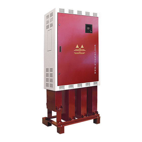
- Page 1 LV CAPACITOR BANKS WITH STATIC SWITCHING EMK SERIES INSTRUCTIONS MANUAL M98118701-03-19A CIRCUTOR, SA...
- Page 2 EMK series SYMBOLS AND WARNINGS Pay attention to the warnings in this manual, which are shown with the following symbols. DANGER: Warns of a risk, which could result in personal injury or material damage. WARNING: Indicates that special attention should be paid to a specific point.
-
Page 3: Table Of Contents
EMK series TABLE OF CONTENTS 1 INTRODUCTION ..........................4 2 SAFETY HAZARDS AND WARNINGS ..................4 ....4 AZARDS ENCOUNTERED DURING THE INSTALLATION AND START UP OF ELECTRICAL EQUIPMENT ..........................4 AFETY WARNINGS 3 RECEPTION, TRANSPORT, HANDLING AND STORAGE ............5 ........................ -
Page 4: Introduction
EMK series INTRODUCTION The purpose of this manual is to assist during the installation, start-up and maintenance of EMK- series low-voltage (LV) capacitor banks with static switching. Carefully read the manual to achieve the best equipment performance. SAFETY HAZARDS AND WARNINGS Hazards encountered during the installation and start-up of electrical equipment. -
Page 5: Reception, Transport, Handling And Storage
Check that all items on the packing list are present. If any discrepancy is noticed upon reception, immediately contact the transport company or CIRCUTOR's after-sales services. Transport, loading and unloading, handling and storage The transport, loading and unloading and handling of the equipment must be carried out with proper precautions and using the proper manual or mechanical tools to prevent damaging the equipment. -
Page 6: Storage
EMK series Fig. 3-2 .-Unloading with a Forklift Storage The following storage recommendations shall be followed for the static capacitor banks: Avoid placing it on uneven surfaces. Do not store in outdoor areas, humid areas or areas exposed to the splashing of water. -
Page 7: Electrical Features
EMK series Electrical features Operating voltage and nominal frequency: / f , listed on the label Design voltage: + 10% (440 V for 400 V equipment) Nominal power and distribution of steps: and composition, (see label) Total loss: Typical 1 W/kvar... -
Page 8: Capacitor Bank Components
EMK series Capacitor bank components Fig. 4-3 shows the different models of EMK static capacitor banks and their essential components. Note that some protection elements are optional and others may be replaced with equivalent models or adapted to the specific application. -
Page 9: Fast Regulator
EMK series From the electrical standpoint, the unit is made up of the following blocks: 4.6.1 Fast regulator Static capacitor banks are equipped with computer Max f, computer Smart f or computer Plus TF fast regulators. The outputs of these regulators are static; that is to say, instead of an output via relay contact they have a semiconductor-based switch which allows them to perform operations in rapid succession, practically every network cycle. -
Page 10: Installation
INSTALLATION Preparation The CIRCUTOR EMK static capacitor banks are prepared for an easy installation and start-up. Remove the equipment's packaging and verify that the unit's electrical features are suitable for connection to the grid at the site to be installed. For this, check the features label located inside the cabinet, next to the regulator, refer to Fig. -
Page 11: Power Circuit
EMK series 5.3.1 Power circuit • Connect input terminals L1, L2 and L3 (power circuit supply) to the grid using proper sized cables in accordance with the National Electric Code or LVD. Generally, the phase cables use the following colour code: L1 (black), L2 (brown), L3 (grey). If a 230 V auxiliary voltage is required, we can use an internal 400V/230V transformer or use the neutral and connect it to terminal N (blue colour cable). - Page 12 EMK series • The rated current of the CT primary winding must be equal to or slightly greater than the size of the installation's main switch. The CT must be able to measure the maximum forecast current expected to be consumed by all the loads.
-
Page 13: Static Capacitor Bank Start-Up
EMK series STATIC CAPACITOR BANK START-UP Before start-up The static capacitor banks include a power factor regulator. In order to perform the proper start-up adjustments, the basics of operation of such regulator must be known. For this reason, all capacitor banks come with the specific manual of the regulator used. Find this manual and have it available for the start-up process. -
Page 14: Tests Once The Capacitor Bank Is Connected And The Regulator Has Been Adjusted
EMK series • Once ensured that the regulator is properly connected, adjust the regulator parameters for the installation you are attempting to compensate. For this, follow the instructions of the particular PF regulator manual, supplied with the equipment. Tests once the capacitor bank is connected and the regulator has been adjusted •... -
Page 15: Maintenance
EMK series MAINTENANCE Safety regulation Keep in mind the safety regulations listed in section 2 of this manual before operating the equipment. The standards, National Electric Code, and applicable laws of the country where the capacitor bank is to be installed or operated should be strictly followed. -
Page 16: Key Points For Inspecting Capacitors
EMK series Table 7-2.- Tightening torques of the cables to the fuse bases THYRISTOR TYPE Tightening of power cables Semikron 3.5 Nm IXYS 3.25 Nm 7.2.4 Key points for inspecting capacitors. • Inspect the cables and terminals. They should not be overheated or blackened. -
Page 17: Environmental Conditions
EMK series Table 7-4.- Nominal consumption of the capacitor steps, depending on its power CURRENT POWER 230 V 400 V 6.28 A 3.6 A 2.5 kvar 12.56 A 7.2 A 5 kvar 7.5 kvar 18.85 A 10.8 A 10 kvar 25.12 A... -
Page 18: Guarantee
Therefore, special care must be taken to not surpass these usage conditions. CIRCUTOR accepts no liability for possible damage to equipment or other parts of the installation, therefore it will not cover any possible penalties resulting from possible failure, improper installation or "improper usage"... -
Page 19: Typical Diagram Of One Step
series TYPICAL DIAGRAM of ONE STEP Instructions Manual M98118701-03-19A... -
Page 20: Declaration Of Conformity
EMK series Declaration of conformity Instructions Manual M98118701-03-19A...
Need help?
Do you have a question about the EMK Series and is the answer not in the manual?
Questions and answers