Advertisement
The simplest ideas are often the best
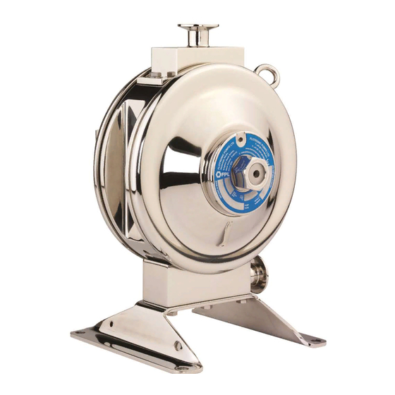
Flotronic 'One - Nut' pumps
Installation Operation and
Maintenance Manual
Diaphragm Leak
Detection System
ATEX APPROVED PUMPS
W:
www.flotronicpumps.co.uk
E:
sales@flotronicpumps.co.uk
S:
www.flotronicspares.co.uk
PLEASE KEEP FOR
FUTURE REFERENCE
ATEX Gas
IIC
Group
compliant
pumps now
available
Advertisement

Subscribe to Our Youtube Channel
Related Manuals for Flotronic One-Nut

Summary of Contents for Flotronic One-Nut
- Page 1 The simplest ideas are often the best Flotronic ‘One - Nut’ pumps Installation Operation and Maintenance Manual Diaphragm Leak Detection System ATEX Gas Group compliant pumps now available ATEX APPROVED PUMPS www.flotronicpumps.co.uk sales@flotronicpumps.co.uk www.flotronicspares.co.uk PLEASE KEEP FOR FUTURE REFERENCE...
-
Page 2: Table Of Contents
Contents Warnings Overview Installation Operation Maintenance Troubleshooting Technical Specifications... -
Page 3: Warnings
Only pump products that are compatible with the pump wetted parts. Do not modify the equipment. Check the device and installation daily and replace any worn or damaged parts immediately using genuine Flotronic Pumps spares. Cables should be routed to avoid damage. Personal Protective Equipment Appropriate personal protective equipment must be worn when operating, servicing or working in the equipment area. -
Page 4: Overview
Overview System Description The leak detection system monitors Flotronic Double Diaphragm pumps for diaphragm failure that could cause contamination of the product being pumped and/or the air control systems internal to the pump and/or the immediate area surrounding the pump. - Page 5 Main Control Unit The main control unit powers the sensors and continuously monitors their output state, ensuring a fast response to any possible diaphragm failure. If the main control unit detects a failure from either sensor the red LED on the front panel will flash.
-
Page 6: Installation
Installation System Connection The main unit is fitted sockets for the connection of the two sensors and solenoid valve and a 150mm hard wired lead fitted with a socket and plug for mains power connection. The sensors are supplied pre-wired for immediate use. The solenoid valve, volt free relay and mains power connection plugs are user connectable using screw terminals internal to the plugs. - Page 7 Power Connection Be sure that the power supply voltage of the area where this unit will be used meets the voltage requirements, 96 – 264Vac @ 50/60Hz, of the main control unit. Please observe the wiring code below, if in any doubt please consult a qualified electrician.
- Page 8 Main Power Connection (continued) L = Live (96-264 Vac) N = Neutral (96-264 Vac) E = Earth Internal screw terminals are lettered. Solenoid Valve Connection 1 = N/C 2 = +24 Vdc (positive) 3 = N/C 4 = -24 Vdc (negative) Internal screw terminals are numbered.
-
Page 9: Operation
Leak Detector Operation During normal operation only the ‘Power’ LED on the main control box will be lit continuously. If a fault develops, i.e. from diaphragm or sensor failure, the ‘Fault’ LED will light flash and the pump will stop. To reset the system after a failure has occurred, and the cause has been rectified, press the ‘Reset’... -
Page 10: Maintenance
Maintenance NOTE: Always disconnect the power supply from the control box before any maintenance or cleaning operation is carried out. Clean Sensors In the event of a diaphragm failure the sensor housing will need to be cleaned to remove all traces of product that may stop the system from resetting and thus the pump from re-starting. - Page 11 Main Control Unit The main control unit requires no maintenance, should a fault be suspected please notify Flotronic Pumps Ltd who can advise the best course of action. It may be necessary to return the item to Flotronic Pumps Ltd for investigation.
- Page 12 Pump Shut Down Check Once it is confirmed that the sensors are functioning correctly the pump should be reassembled to perform the ‘pump shut down check’. To perform this check: Connect the power supply to the main control unit. Turn on the air supply to the pump. The pump should not start and the red LED indicator on the main control unit should be flashing.
-
Page 13: Troubleshooting
Check power supply lead for and system does not damage. function Confirm unit is receiving power. Main Control Unit fault Contact Flotronic Pumps Ltd for advice. Fault LED flashing Diaphragm failure Strip pump and check for diaphragm failure or the presence of liquid in the air chamber. -
Page 14: Technical Specifications
Technical Data Main Control Unit Input Voltage Range 96-264Vac, 50/60Hz Main Control Unit Operating Temp. Range 0 - 40°c Main Control Unit IP Rating IP65 Maximum Power Consumption 30 Watts Sensors Maximum Sensor Pressure 7.2 Barg (105psi) Sensor Temp. Range -25°c –... - Page 15 Ricebridge Works, Brighton Road, Bolney, West Sussex RH17 5NA. UK Tel: +44 (0)1444 881871 Fax: +44 (0)1444 881860 Email: sales @ flotronicpumps.com Web: www.flotronicpumps.com For authentic pump spares go to: www.flotronicspares.co.uk ‘Flotronic’ is a UK registered trade mark. Specifications subject to change without notice.
Need help?
Do you have a question about the One-Nut and is the answer not in the manual?
Questions and answers