Table of Contents
Advertisement
The simplest ideas are often the best
Flotronic 'One - Nut' pumps
Installation Operation and
Maintenance Manual
Flotronic One-Nut Air Driven Double Diaphragm Pumps
and Ancillary Equipment
ATEX APPROVED PUMPS
W:
www.flotronicpumps.co.uk
E:
sales@flotronicpumps.co.uk
S:
www.flotronicspares.co.uk
PLEASE KEEP FOR
FUTURE REFERENCE
ATEX Gas
IIC
Group
compliant
pumps now
available
Advertisement
Table of Contents

Subscribe to Our Youtube Channel
Related Manuals for Flotronic F Slim series

Summary of Contents for Flotronic F Slim series
- Page 1 The simplest ideas are often the best Flotronic ‘One - Nut’ pumps Installation Operation and Maintenance Manual Flotronic One-Nut Air Driven Double Diaphragm Pumps and Ancillary Equipment ATEX Gas Group compliant pumps now available ATEX APPROVED PUMPS www.flotronicpumps.co.uk sales@flotronicpumps.co.uk www.flotronicspares.co.uk...
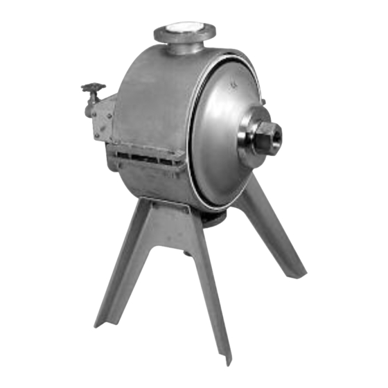
- Page 2 The Pumps SLIM F Series award-winning metal pumps Machined from solid material, these compact and self-draining pumps are available in 316 stainless steel, aluminium and also exotic metals, including Hastelloy ® . These pumps can be used in a wide range of industries including chemical, cosmetic, paints, pharmaceutical, adhesive and hygienic applications.
-
Page 3: Table Of Contents
Contents Section No. Description Page Section 1 General Information Section 2 Training Section 3 Limitation of Use Section 4 Essential Safety Requirements (ESR) Section 5 ATEX Safety Manual Section 6 Installation Section 7 Hydrostatic Testing Section 8 Operation of Pumps & Torque Figures Section 9 Noise Levels Section 10... -
Page 4: General Information
Formal training at FPL Premises by our skilled training personnel using visual aids, ‘hands on’ equipment, etc, at an agreed cost to be confirmed. It is your responsibility to request your preferred training method now. Flotronic will not consider responsibility for ongoing breakdowns etc, if training has not been given. -
Page 5: Limitation Of Use
Flotronic estimators. All performance figures, temperatures, flow rates, dimensions & other details are subject to change without notice. -
Page 6: Essential Safety Requirements (Esr)
Essential Safety Requirements (ESR) Section 4 - Essential Safety Requirements (ESR) ATEX DIRECTIVE 2014/34/EU (EXPLOSION HAZARD SAFETY) All FPL products that are certified to comply with the Directive also carry a specific ATEX Safety Manual (Section 5) which must be referred to in conjunction with this manual. It is the responsibility of the user to ensure that the equipment is correctly rated for the environment in which it is to be used. - Page 7 Health Hazard Warning Health Hazard Warning Please note that PTFE is used in FPL pumps when specified in diaphragms, seals, seats and other components. At temperatures up to 250°C polytetrafluoroethylene (PTFE) is completely inert so that on the rare occasions when the diaphragm fails or cracks,there is no direct danger from these components, other than if particles are allowed to be carried into the process liquids.
-
Page 8: Atex Safety Manual
ATEX Safety Manual Section 5 - ATEX Safety Manual For Air Driven Diaphragm Pumps and Ancillary Equipment User Instructions to ensure compliance with European Directive 2014/34/EU GENERAL ATEX Directive 2014/34/EU Disclaimer Personnel qualifications and training SAFETY Summary of safety marking Products used in potentially explosive atmospheres Scope of compliance Marking... -
Page 9: General
Explosive Atmosphere check the nameplate and the Certification provided. 1.2 Disclaimer Information in these User Instructions is believed to be reliable. In spite of all the efforts of Flotronic Pumps Ltd to provide sound and all necessary information, the content of this Manual may appear insufficient and is not guaranteed by Flotronic Pumps Ltd as to its completeness or accuracy. -
Page 10: Safety
Where Flotronic Pumps Ltd has supplied only the bare pump, the Ex rating applies only to the pump. The party responsible for installing the pump shall select any additional equipment, with the necessary... -
Page 11: Marking
ENSURE THE EQUIPMENT TEMPERATURE CLASS IS SUITABLE FOR THE HAZARD ZONE 2.5.1 Pump liquid temperature Pumps have a temperature class as stated in the ATEX Ex rating on the nameplate. These are based on a maximum ambient of 40 C (104 F); refer to Flotronic Pumps for higher ambient temperatures. -
Page 12: Preventing The Build Up Of Explosive Mixtures
Maximum Temperature limit of liquid handled Class to surface temperature depending on material and construction variant. EN 13463–1 permitted Consult Flotronic Pumps Ltd. C (185 Consult Flotronic Pumps Ltd C (212 Consult Flotronic Pumps Ltd C (275 C (221 C (392... -
Page 13: Preventing Leakage
ATEX Safety Manual Avoid electrostatic charge: Do not rub non-metallic surfaces with a dry cloth for cleaning etc; ensure the cloth is damp. 2.8 Preventing leakage The pump must only be used to handle liquids for which it has been approved to have the correct corrosion resistance. -
Page 14: Additional Safety Instructions
ATEX Safety Manual 2.10 Additional Safety Instructions a Pumps and ancillary equipment must be drained, cleaned and decontaminated prior to any change of duty. b Where pumps and ancillary equipment contain non-conductive plastic wetted components, dismantling for maintenance must take place in a safe area away from the flammable hazard, or the equipment made safe by purging with nitrogen. - Page 15 Your Notes...
-
Page 16: Installation
Flotronic Pump connections are designed of adequate thickness to absorb normal pipe loads/ connections. Do not over tighten or force pipes into threads (particularly female plastic threads). - Page 17 Installation SLIM Stainless steel range Diaphragm elivery Size Wt/kg Diameter ⁄ ” - 1” 159 117 332 109 175 215 92 160 7” ⁄ ” - 1” 172 129 425 145 217 255 109 203 10” ⁄ ”-2” 207 163 466 163 242 290 109 203 10”...
-
Page 18: Hydrostatic Testing
PUMPS/DAMPERS WITH JACKETED BODY/MANIFOLDS The jacketing of all Flotronic Pumps/Dampers supplied before 31/12/98 has a maximum working pressure of 2 Bar G. Under no circumstances must super heated steam be used in these jackets. -
Page 19: Operation Of Pumps & Torque Figures
& Torque Figures Section 8 - Operation of Pumps & Torque Figures For pump performance curves refer to the Flotronic general product brochure or company website www.flotronicpumps.co.uk. Before the pump is put into service and after any maintenance, tighten the fastenings to the torque figures given below;... - Page 20 Capacities and flow rates may vary if other types of 5 port valves are fitted. Flotronic pumps reserve the right to supply pumps fitted with alternative types of valve without notice.
-
Page 21: Noise Levels
In certain circumstances, this air can carry pumped liquid in it which can escape to the environment through the silencers. Flotronic, therefore, recommend pumps are purchased with either Guardian or Sentinel systems and promote this at time of sale. -
Page 22: Servicing & Diaphragm Fitting Instructions
Servicing & Diaphragm Fitting Instructions Section 10 - Servicing & Diaphragm Fitting Instructions All “One Nut” fast maintenance FPL pumps have a common construction through the horizontal centre line of the pump, with the single nut being a device which holds the air system, diaphragms and thrust tube assembly together, via the tie rod. - Page 23 Servicing & Diaphragm Fitting Instructions 4. fit thrust tube with one diaphragm attached passing tube through the centre body. When tension divider seals are fitted,use the plastic nose cone (Supplied with pump - if in doubt contact FPL), to aid assembly. 5.
- Page 24 Servicing & Diaphragm Fitting Instructions FITTING REINFORCED DIAPHRAGMS On pump applications that cause a positive pressure greater than 2 bar to act on the diaphragm wetted face when supporting air pressure is not present, e.g. in CIP or high suction head systems, reinforced diaphragms will normally be specified.
- Page 25 Servicing & Diaphragm Fitting Instructions Before carrying out these processes it may be necessary, and is certainly advisable, to change the divider seal fitted in the centre section of the pump body. To carry out this procedure, refer to the individual section covering the model of pump being serviced.
-
Page 26: F Series 500 Style Plastic & Aluminium Pumps
F Series 500 Style Plastic & Aluminium Pumps Section 11 - F Series 500 Style Plastic & Aluminium Pumps... - Page 27 F Series 500 Style Plastic & Aluminium Pumps Section 11 - F Series 500 Style Plastic & Aluminium Pumps All previous maintenance instructions up to & including Section 10 apply to F series 500 style pumps but in addition, the following procedures apply. PUMPS WITH 7”, 10”...
- Page 28 F Series 500 Style Plastic & Aluminium Pumps While gripping the seal, twist the seal so that the face can be inserted into the groove. Then work the remainder of the seal into the groove, finally pushing the seal down with a wooden handle from a screwdriver or similar.
- Page 29 F Series 500 Style Plastic & Aluminium Pumps Thrust tube sleeves may be either welded together permanently or alternatively, may have an inner ‘O’ ring inside the sleeve. Removal of this ‘O’ ring and replacement can be carried out by pulling the two halves of the thrust sleeve tube apart, prizing out the old ring and fitting with new components supplied.
-
Page 31: F Series 710 Style Stainless Steel Pumps
F Series 710 Style Stainless Steel Pumps Section 12 - F Series 710 Style Stainless Steel Pumps... - Page 32 F Series 710 Style Stainless Steel Pumps Section 12 - F Series 710 Style Stainless Steel Pumps All previous maintenance and other instructions up to and including Section 10 given earlier apply to F Series 710 style pumps. In addition, the following procedures apply. Access to valves and seats is carried out by first disconnecting process pipe-work and undoing the two or four bolts which connect the suction and delivery manifolds together, and which are located between the pumping chambers and adjacent to the outside body of the pump.
- Page 33 F Series 710 Style Stainless Steel Pumps PROCEDURE FOR FITTING DIVIDER SEAL (PTFE) Divider seals can be fitted into F Series 710 Style pumps with 10” diameter diaphragms. First prise out the old divider seal from the groove in the centre of the pump body, and refitting, by inserting a new divider seal up into the inner groove as far as possible by bending the new seal into position.
- Page 34 F Series 710 Style Stainless Steel Pumps On 2” & 3” F Series 710 Style pumps with 14” diameter diaphragms the divider seal assembly is in two parts. On one side of the body there is an elongated groove containing a flat seal which can first be removed by sliding the seal upwards into the elongated section of groove, then by gripping the lower part of the seal, it can be pulled out.
-
Page 36: F Series Good Food Style Pump
F Series Good Food Style Pump Section 13 - F Series Good Food Style Pump... - Page 37 F Series Good Food Style Pump Section 13 - F Series Good Food Style Pump All previous maintenance and other instructions up to and including Section 10 given earlier, apply to the F Series Good Food pumps. In addition, the following procedures apply. Access to valves and seats is carried out by first disconnecting process pipe-work and undoing the top and bottom handles which screw through the cross bar across the top and bottom of the pump.
- Page 39 F Series Good Food Style Pump Cleaning Procedures FPL pumps for food and pharmaceutical applications have been designed to minimise areas where soils can accumulate with consequent user problems. Areas, which may be liable to accommodate soils, include the connecting faces between diaphragms and pump body and the divider seal and bushes where fitted.
-
Page 40: F Series Slim Style Metallic Pumps
F Series Slim Style Metallic Pumps Section 14 - F Series Slim Style Metallic Pumps... - Page 41 F Series Slim Style Metallic Pumps Section 14 - F Series Slim Style Metallic Pumps All previous maintenance and other instructions up to and including Section 10 given earlier apply to F Series Slim Style Metallic Pumps. In addition the following procedures apply. After disconnecting the process pipework, access to the delivery and suction valve balls for inspection and replacement may be achieved as follows.
- Page 42 F Series Slim Style Metallic Pumps BODY AND MANIFOLD DRAINING Suction and delivery valve ball lifters may be fitted to F Series Slim Style metallic pumps as an option where rapid pump draining is required. On pumps fitted with this option there are external levers for operating the suction and delivery valve balls. The levers must be turned to the “run”...
-
Page 44: F Series 'K' Style Chemflo All Ptfe
F Series ‘K’ Style Chemflo All PTFE Section 15 - F Series ‘K’ Style Chemflo All PTFE... - Page 45 F Series ‘K’ Style Chemflo All PTFE Section 15 - F Series ‘K’ Style Chemflo All PTFE All previous instructions up to and including Section 10 apply in addition to the following: ACCESS TO VALVES AND SEATS The air system, both diaphragms and thrust tube must be removed as in Section 10. Disconnect the process pipework from the pump and remove the suction and delivery connector sleeves.
- Page 47 F Series ‘K’ Style Chemflo All PTFE The temporary supporting nuts can be removed to allow the body to locate in the lower housing carefully aligning the suction port on the suction body register collar. Note the body may not locate fully at this stage due to the suction seat plugs standing proud.
-
Page 48: Air Valves
Air Valves Section 16 - Air Valves... - Page 49 Air Valves Section 16 - Air Valves This section is common to all pumps. All air valves are bolted to a mounting plate using either 3 or 4 bolts which, after removal, will allow the air valve to be examined in detail. Note that there will be ‘O’ ring seals and jointing materials between the air valve and the plate which should be examined and replaced if necessary.
-
Page 50: Pulsation Dampers
Pulsation Dampers Section 17 - Pulsation Dampers... - Page 51 Pulsation Dampers Section 17 - Pulsation Dampers This section is common to all pumps. Pulsation dampers are obtainable to be fitted to FPL pumps but vary depending upon the individual model considered. The maintenance instructions given below apply to all models, although the mounting of the damper on to the pump may vary slightly.
- Page 52 Pulsation Dampers...
- Page 53 Assembly of New Diaphragm ASSEMBLY Insert the spool valve rod into the diaphragm and tighten, securing with a small amount of thread locking compound. Do not use serrated grips or other sharp objects as they will damage this rod. Check that the ‘O’ rings are correctly fitted inside the spool valve body, if damaged these ‘O’ rings must be replaced.
- Page 54 Your Notes...
- Page 55 Rupture Protection Barriers & Alarm Systems Section 18 - Rupture Protection Barriers & Alarm Systems...
- Page 56 Rupture Protection Barriers & Alarm Systems Section 18 - Rupture Protection Barriers & Alarm Systems ALL PUMP SERIES RUPTURE PROTECTION PACKAGE INSTALLATION MAINTENANCE & OPERATION INSTRUCTIONS The following instructions must be read in conjunction with the individual instructions relating to the applicable Pump Series and apply to the horizontal centre line assembly only, as follows: ACCESS TO DIAPHRAGMS Before carrying out any maintenance or servicing, the air system and the connections must be...
- Page 57 Under no circumstances should this diaphragm be fitted with the PTFE (white) side facing outwards. Ensure that the connection tapping on the separator ring is in the correct position for the Flotronic Sentinel Alarm System, or your own pressure switch if required/fitted. All Pumps with 10” diameter diaphragms...
- Page 58 Note: This special tooling assembly is only necessary because of the special nature of environmentally protected air driven double diaphragm pump. Normal 2 diaphragm Flotronic Pumps do not require any special tooling to fit diaphragms.
- Page 59 Your Notes...
- Page 60 Rupture Protection Barriers & Alarm Systems SENTINEL ALARM - OPERATING INSTRUCTIONS 1. Vacuum isolating valve must be open. 2. Air valves 1 and 2 must be closed. 3. Open air valve 1 to allow alarm unit to prime. 4. Alarm system is primed when vacuum gauge reading has stabilised at approximately -0.8 bar dependent on air supply.
-
Page 62: Count & Stop Pumps All Series
Count & Stop Pumps All Series Section 19 - Count & Stop Pumps - All Series... - Page 63 The preset value can be selected anywhere between 1 and 99999. Connections Pre-assembled at the Flotronic factory prior to despatch. actual value pre-set value Pre-set...
-
Page 64: Trouble Shooting
Pump cycles when pump is stalled against a closed head? This is normal with Flotronic and assists the anti-stall mechanism of the pump. It is normal for the pump to cycle once or twice a minute, but if it cycles more, replace the divider seal. - Page 65 Your Notes...
-
Page 66: Further Assistance
The information that is given in this manual is given in good faith and is accurate at the time of going to press. Flotronic reserve the right to modify and change any of our products, without notice, in accordance with our policy for continued product improvement... - Page 67 Your Notes...
- Page 68 Your Notes...
-
Page 69: Further Assistance
If you require any further assistance, please call us on our Helpline Number 01444 881871 or Email us at sales @ flotronicpumps.co.uk Flotronic Pumps Limited also provide: • Planned maintenance programmes to suit your needs carried out by one of our Specialist Engineers •... - Page 70 Tel: +44 (0)1444 881871 Fax: +44 (0)1444 881860 Email: sales @ flotronicpumps.co.uk Web: www.flotronicpumps.co.uk For authentic pump spares go to: www.flotronicspares.co.uk ® Hastelloy is a registered trademark of Haynes International. ‘Flotronic’ is a UK registered trade mark. Specifications subject to change without notice.
Need help?
Do you have a question about the F Slim series and is the answer not in the manual?
Questions and answers