Table of Contents
Advertisement
Quick Links
Quick Start
Thank you for purchasing the MSI®
B450M BAZOOKA MAX WIFI
motherboard. This
Quick Start section provides demonstration diagrams about how to install your
computer. Some of the installations also provide video demonstrations. Please link to
the URL to watch it with the web browser on your phone or tablet. You may have even
link to the URL by scanning the QR code.
Preparing Tools and Components
AMD
AM4 CPU
®
CPU Fan
Chassis
DDR4 Memory
Power Supply Unit
Graphics Card
Thermal Paste
SATA Hard Disk Drive
SATA DVD Drive
A Package of Screws
Phillips Screwdriver
1
Quick Start
Advertisement
Table of Contents

Related Manuals for MSI B450M BAZOOKA MAX WIFI


Summary of Contents for MSI B450M BAZOOKA MAX WIFI
-
Page 1: Quick Start
Quick Start Thank you for purchasing the MSI® B450M BAZOOKA MAX WIFI motherboard. This Quick Start section provides demonstration diagrams about how to install your computer. Some of the installations also provide video demonstrations. Please link to the URL to watch it with the web browser on your phone or tablet. You may have even link to the URL by scanning the QR code. -
Page 2: Safety Information
Safety Information y The components included in this package are prone to damage from electrostatic discharge (ESD). Please adhere to the following instructions to ensure successful computer assembly. y Ensure that all components are securely connected. Loose connections may cause the computer to not recognize a component or fail to start. -
Page 3: Installing A Processor
Installing a Processor https://youtu.be/Xv89nhFk1vc Quick Start... - Page 4 Important If you are installing the screw-type CPU heatsink, please follow the figure below to remove the retention module first and then install the heatsink. Quick Start...
-
Page 5: Installing Ddr4 Memory
Installing DDR4 memory http://youtu.be/T03aDrJPyQs DIMMA1 DIMMA2 DIMMA2 DIMMA2 DIMMB2 DIMMB1 DIMMB2 Quick Start... -
Page 6: Connecting The Front Panel Header
Connecting the Front Panel Header http://youtu.be/DPELIdVNZUI Power LED Power Switch JFP1 Reserved HDD LED Reset Switch HDD LED + Power LED + HDD LED - Power LED - Reset Switch Power Switch JFP1 Reset Switch Power Switch Reserved No Pin HDD LED - HDD LED HDD LED +... -
Page 7: Installing The Motherboard
Installing the Motherboard https://youtu.be/wWI6Qt51Wnc Torque: 3 kgf·cm* *3 kgf·cm = 0.3 N·m = 2.6 lbf·in Quick Start... -
Page 8: Connecting The Power Connectors
Connecting the Power Connectors http://youtu.be/gkDYyR_83I4 CPU_PWR1 ATX_PWR1 Quick Start... -
Page 9: Installing Sata Drives
Installing SATA Drives http://youtu.be/RZsMpqxythc Quick Start... -
Page 10: Installing A Graphics Card
Installing a Graphics Card http://youtu.be/mG0GZpr9w_A Quick Start... -
Page 11: Connecting Peripheral Devices
Connecting Peripheral Devices Quick Start... -
Page 12: Power On
Power On Quick Start... -
Page 13: Table Of Contents
Contents Quick Start ......................1 Preparing Tools and Components................1 Safety Information ....................2 Installing a Processor .................... 3 Installing DDR4 memory ..................5 Connecting the Front Panel Header ..............6 Installing the Motherboard ..................7 Connecting the Power Connectors ................ 8 Installing SATA Drives .................... - Page 14 Onboard LEDs ...................... 39 EZ Debug LED ....................... 39 Installing OS, Drivers & Utilities ................. 40 Installing Windows® 10 ..................40 Installing Drivers ....................40 Installing Utilities ....................40 BIOS Setup ......................41 Entering BIOS Setup ..................... 41 Resetting BIOS ...................... 42 Updating BIOS .......................
-
Page 15: Specifications
∙ Dual channel memory architecture ∙ Supports non-ECC UDIMM memory ∙ Supports un-buffered memory * Please refer www.msi.com for more information on compatible memory. ∙ 1x PCIe 3.0 x16 slot (PCI_E1)* ▪ 1st, 2nd and 3rd Gen AMD Ryzen™ support x16 mode ▪... - Page 16 Continued from previous page ∙ 1x Realtek® 8111H Gigabit LAN controller ∙ Wi-Fi/Bluetooth expansion module with Intel Single Band Wireless-AC 3168 chip ∙ Supports Wi-Fi 802.11 a/b/g/n/ac, single band (2.4GHz, Wireless LAN & 5GHz) up to 433 Mbps speed. Bluetooth® ∙...
- Page 17 Continued from previous page 1x 24-pin ATX main power connector 1x 8-pin ATX 12V power connector 4x SATA 6Gb/s connectors 1x M.2 slot (Key M) 1x USB 3.2 Gen1 connector (supports additional 2 USB 3.2 Gen1 ports) 2x USB 2.0 connectors (supports additional 4 USB 2.0 ports) 1x 4-pin CPU Fan connector 2x 4-pin system Fan connectors Internal Connectors...
- Page 18 Continued from previous page ∙ Drivers ∙ DRAGON CENTER ∙ MSI App Player(BlueStacks) Software ∙ Open Broadcaster Software (OBS) ∙ CPU-Z MSI GAMING ∙ Google Chrome™, Google Toolbar, Google Drive ∙ Norton™ Internet Security Solution ∙ Gaming Mode ∙ Gaming Hotkey ∙...
- Page 19 Continued from previous page ∙ Audio ▪ Audio Boost ∙ Storage ▪ Turbo M.2 ∙ Fan ▪ Gaming Fan Control ∙ LED ▪ Mystic Light ▪ Mystic Light Extension (RGB) ▪ Mystic Light Extension (RAINBOW) ▪ EZ DEBUG LED ∙ Protection Special Features ▪...
-
Page 20: Package Contents
Package contents Please check the contents of your motherboard package. It should contain: Motherboard B450M BAZOOKA MAX WIFI Cable SATA 6Gb/s Cables (2 cables/pack) WiFi Antenna Case Badge Accessories Product Registration Card M.2 screws (3 pcs./pack) Application DVD Driver DVD... -
Page 21: Block Diagram
Block Diagram HDMI 2 Channel DDR4 Memory 4x USB 3.2 Gen1 PCIe x16 NCT6795 Super I/O Realtek ALC892 PS/2 Mouse / Keyboard Audio Jacks 1 x M.2 PCIe x4 CHIPSET RTL8111H LAN 4x SATA 6Gb/s INTEL WIFI 3168 8x USB 2.0 2x USB 3.2 Gen1 Block Diagram... -
Page 22: Rear I/O Panel
Rear I/O Panel Line-in Gigabit LAN Line-out PS/2 USB 2.0 Mic in USB 3.2 Gen1 USB 2.0 Wi-Fi Antenna connectors LAN Port LED Status Table Link/ Activity LED Speed LED Status Description Status Description No link 10 Mbps connection Yellow Linked Green 100 Mbps connection... - Page 23 ∙ Device Selection - allows you to select a audio output source to change the related options. The check sign indicates the devices as default. ∙ Application Enhancement - the array of options will provide you a complete guidance of anticipated sound effect for both output and input device. ∙...
- Page 24 Installing antennas 1. Screw the antennas tight to the antenna connectors as shown below. 2. Orient the antennas. Rear I/O Panel...
-
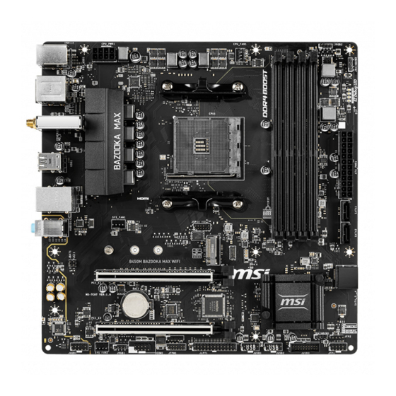
Page 25: Overview Of Components
Overview of Components DIMMA1 CPU Socket DIMMA2 DIMMB1 CPU_PWR1 CPU_FAN1 DIMMB2 JRGB2 JRAINBOW2 ATX_PWR1 SATA1 SYS_FAN1 SATA2 M2_1 JCI1 JBAT1 PCI_E1 SATA▼3▲4 JRAINBOW1 PCI_E2 JFP2 JFP1 JUSB3 JAUD1 SYS_FAN2 JUSB2 JRGB1 JUSB1 JCOM1 JTPL1 JTPM1 Overview of Components... - Page 26 Component Contents Port Name Port Type Page CPU_FAN1, SYS_FAN1~2 Fan Connectors CPU_PWR1, ATX_PWR1 Power Connectors CPU Socket AM4 Socket DIMMA1/A2/B1/B2 DIMM Slots JAUD1 Front Audio Connector JBAT1 Clear CMOS (Reset BIOS) Jumper JCI1 Chassis Intrusion Connector JCOM1 Serial Port Connector JFP1, JFP2 Front Panel Connectors JLPT1...
-
Page 27: Processor Socket
Any attempt to operate beyond product specifications is not recommended. MSI® does not guarantee the damages or risks caused by inadequate operation beyond product specifications. Overview of Components... -
Page 28: Dimm Slots
Due to AM4 CPU/memory controller official specification limitation, the frequency of ∙ memory modules may operate lower than the marked value under the default state. Please refer www.msi.com for more information on compatible memory. Overview of Components... -
Page 29: Pci_E1~2: Pcie Expansion Slots
*** For Athlon™ with Radeon™ Vega Graphics Processors Important ∙ If you install a large and heavy graphics card, you need to use a tool such as MSI Gaming Series Graphics Card Bolster to support its weight to prevent deformation of the slot. -
Page 30: M2_1: M.2 Slot (Key M)
M2_1: M.2 Slot (Key M) ⚽ Video Demonstration Watch the video to learn how to Install M.2 module. http://youtu.be/JCTFABytrYA 1. Move the position of the standoffs according to your M.2 SSDs length if need. 2. Insert your M.2 SSD into the M.2 slot at a 30-degree angle. -
Page 31: Cpu_Pwr1, Atx_Pwr1: Power Connectors
CPU_PWR1, ATX_PWR1: Power Connectors These connectors allow you to connect an ATX power supply. CPU_PWR1 Ground +12V Ground +12V Ground +12V Ground +12V +3.3V +3.3V +3.3V -12V Ground Ground PS-ON# Ground Ground Ground ATX_PWR1 Ground Ground PWR OK 5VSB +12V +12V +3.3V Ground... -
Page 32: Cpu_Fan1, Sys_Fan1~2: Fan Connectors
CPU_FAN1, SYS_FAN1~2: Fan Connectors Fan connectors can be classified as PWM (Pulse Width Modulation) Mode or DC Mode. PWM Mode fan connectors provide constant 12V output and adjust fan speed with speed control signal. DC Mode fan connectors control fan speed by changing voltage. You can follow the instruction below to adjust the fan connector to PWM or DC Mode. -
Page 33: Jusb3: Usb 3.2 Gen1 Connector
No Pin Important Note that the VCC and Ground pins must be connected correctly to avoid possible ∙ damage. In order to recharge your iPad,iPhone and iPod through USB ports, please install ∙ MSI DRAGON CENTER utility. Overview of Components... -
Page 34: Jtpm1: Tpm Module Connector
JTPM1: TPM Module Connector This connector is for TPM (Trusted Platform Module). Please refer to the TPM security platform manual for more details and usages. LPC Clock 3V Standby power LPC Reset 3.3V Power LPC address & data pin0 Serial IRQ LPC address &... -
Page 35: Jlpt1: Parallel Port Connector
JLPT1: Parallel Port Connector This connector allows you to connect the optional parallel port with bracket. RSTB# AFD# PRND0 ERR# PRND1 PINIT# PRND2 LPT_SLIN# PRND3 Ground PRND4 Ground PRND5 Ground PRND6 Ground PRND7 Ground ACK# Ground BUSY Ground Ground SLCT No Pin JCOM1: Serial Port Connector This connector allows you to connect the optional serial port with bracket. -
Page 36: Jci1: Chassis Intrusion Connector
JCI1: Chassis Intrusion Connector This connector allows you to connect the chassis intrusion switch cable. Normal Trigger the chassis intrusion event (default) Using chassis intrusion detector 1. Connect the JCI1 connector to the chassis intrusion switch/ sensor on the chassis. 2. -
Page 37: Jrgb1~2: Rgb Led Connectors
(12V/G/R/B) with the maximum power rating of 3A (12V). Always turn off the power supply and unplug the power cord from the power outlet ∙ before installing or removing the RGB LED strip. Please use MSI’s software to control the extended LED strip. ∙ Overview of Components... -
Page 38: Jrainbow1~2: Addressable Rgb Led Connectors
(5V). In the case of 20% brightness, the connector supports up to 200 LEDs. ∙ Always turn off the power supply and unplug the power cord from the power outlet before installing or removing the RGB LED strip. Please use MSI’s software to control the extended LED strip. ∙ Overview of Components... -
Page 39: Onboard Leds
Onboard LEDs EZ Debug LED These LEDs indicate the debug status of the motherboard. CPU - indicates CPU/ DRAM is not detected or fail. DRAM - indicates DRAM is not detected or fail. VGA - indicates GPU is not detected or fail. BOOT - indicates the booting device is not detected or fail. -
Page 40: Installing Os, Drivers & Utilities
Installing OS, Drivers & Utilities Please download and update the latest utilities and drivers at www.msi.com Installing Windows® 10 1. Power on the computer. 2. Insert the Windows® 10 installation disc/USB into your computer. 3. Press the Restart button on the computer case. -
Page 41: Bios Setup
BIOS Setup The default settings offer the optimal performance for system stability in normal conditions. You should always keep the default settings to avoid possible system damage or failure booting unless you are familiar with BIOS. ⚠ Important ∙ BIOS items are continuously update for better system performance. Therefore, the description may be slightly different from the latest BIOS and should be for reference only. -
Page 42: Resetting Bios
Updating BIOS Updating BIOS with M-FLASH Before updating: Please download the latest BIOS file that matches your motherboard model from MSI website. And then save the BIOS file into the USB flash drive. Updating BIOS: 1. Press Del key to enter the BIOS Setup during POST. -
Page 43: Ez Mode
EZ Mode At EZ mode, it provides the basic system information and allows you to configure the basic setting. To configure the advanced BIOS settings, please enter the Advanced Mode by pressing the Setup Mode switch or F7 function key. Screenshot A-XMP switch Setup Mode switch... - Page 44 ∙ Information display - click on the CPU, Memory, Storage, Fan Info and Help buttons on left side to display related information. ∙ Function buttons - enable or disable the LAN Option ROM, CSM/UEFI, HD audio controller, AHCI/RAID, CPU Fan Fail Warning Control, ErP Ready and BIOS Log Review by clicking on their respective button.
-
Page 45: Advanced Mode
Advanced Mode Press Setup Mode switch or F7 function key can switch between EZ Mode and Advanced Mode in BIOS setup. Screenshot A-XMP switch Setup Mode switch Search Language System information GAME BOOST switch Boot device priority bar BIOS menu BIOS menu selection selection... -
Page 46: Settings
SETTINGS System Status ▶ System Date Sets the system date. Use tab key to switch between date elements. The format is <day> <month> <date> <year>. <day> Day of the week, from Sun to Sat, determined by BIOS. Read-only. <month> The month from Jan. through Dec. <date>... - Page 47 Disables this function. ▶ PCIe SlotX Lanes Configuration PCIe lanes configuration is for MSI M.2 Xpander / MSI M.2 Xpander-Z / Other M.2 PCIe storage card. The options in this item will vary with the installed processor. ▶ ACPI Settings Sets ACPI parameters of onboard power LED behaviors.
- Page 48 ▶ LAN Option ROM [Disabled] Enables or disables the legacy network Boot Option ROM for detailed settings. This item will appear when Onboard LAN Controller is enabled. [Enabled] Enables the onboard LAN Boot ROM. [Disabled] Disables the onboard LAN Boot ROM. ▶...
- Page 49 ▶ Initiate Graphic Adapter [PEG] (optional) Selects a graphics device as the primary boot device. [IGD] Integrated Graphics Display. [PEG] PCI-Express Graphics Device. ▶ Integrated Graphics [Auto] (optional) If set to Force, BIOS will enable the integrated graphics controller. ▶ UMA Frame Buffer Size [Auto] (optional) Selects a fixed amount of system memory allocated to the onboard graphics.
- Page 50 ▶ Device Mode [STD Printer Mode] Selects an operating mode for parallel port. [STD Printer Mode] Printer port mode [SPP] Standard Parallel Port mode [EPP-1.9 and SPP Mode] Enhanced Parallel Port-1.9 mode + Standard Parallel Port mode. ▶ Power Management Setup Sets system Power Management of ErP and AC Power Loss behaviors.
- Page 51 ▶ Wake Up Event By [BIOS] Selects the wake up event by BIOS or operating system. [BIOS] Activates the following items, set wake up events of these items. [OS] The wake up events will be defined by OS. ▶ Resume By RTC Alarm [Disabled] Disables or enables the system wake up by RTC Alarm.
-
Page 52: Boot
▶ Realtek PCIe GBE Family Controller Shows driver information and configuration of the ethernet controller parameter. Boot Sets the sequence of system boot devices. ▶ Full Screen Logo Display [Enabled] Enables or disables to show the full screen logo while system POST. [Enabled] Shows the logo in full screen. -
Page 53: Security
Security ▶ Administrator Password Sets administrator password for system security. User has full rights to change the BIOS items with administrator password. After setting the administrator password, the state of this item will show Installed. ▶ User Password Sets User Password for system security. User has limited rights to change the BIOS items with user password. -
Page 54: Save & Exit
▶ Chassis Intrusion Configuration Press Enter to enter the sub-menu. ▶ Chassis Intrusion [Disabled] Enables or disables recording messages while the chassis is opened. This function is ready for the chassis equips a chassis intrusion switch. [Enabled] Once the chassis is opened, the system will record and issue a warning message. - Page 55 ⚠ Important Overclocking your PC manually is only recommended for advanced users. ∙ Overclocking is not guaranteed, and if done improperly, it could void your warranty ∙ or severely damage your hardware. ∙ If you are unfamiliar with overclocking, we advise you to use GAME BOOST function for easy overclocking.
- Page 56 ▶ DRAM Frequency [Auto] Sets the DRAM frequency. Please note the overclocking behavior is not guaranteed. ▶ Adjusted DRAM Frequency Shows the adjusted DRAM frequency. Read-only. ▶ Memory Try It ! [Disabled] It can improve memory compatibility or performance by choosing optimized memory preset.
- Page 57 ▶ Memory Changed Detect [Enabled]* Enables or disables the system to issue a warning message during boot when the memory has been replaced. [Enabled] The system will issue a warning message during boot and then you have to load the default settings for new devices. [Disabled] Disables this function and keeps the current BIOS settings.
- Page 58 ▶ Relaxed EDC throttling [Auto] (optional) Relaxed EDC throttling reduces the amount of time the processor will throttle the cores. [Auto] AMD's recommendation [Enabled] Reduce the amount of time the processor will throttle. [Disabled] Part-specific EDC throttling protection enabled. ▶ AMD Cool’n’Quiet [Enabled] The Cool’n’Quiet technology can effectively and dynamically lower CPU speed and power consumption.
-
Page 59: M-Flash
M-FLASH provides the way to update BIOS with a USB flash drive. Please download the latest BIOS file that matches your motherboard model from MSI website, save the BIOS file into your USB flash drive. And then follow the steps below to update BIOS. -
Page 60: Oc Profile
OC PROFILE ▶ Overclocking Profile 1/ 2/ 3/ 4/ 5/ 6 Overclocking Profile 1/ 2/ 3/ 4/ 5/ 6 management. Press Enter to enter the sub-menu. ▶ Set Name for Overclocking Profile 1/ 2/ 3/ 4/ 5/ 6 Name the current overclocking profile. ▶... -
Page 61: Hardware Monitor
HARDWARE MONITOR Temperature & Speed Fan Manage Setting Buttons Temperature/ Voltage display ▶ Temperature & Speed Shows the current CPU temperature, system temperature and fans' speeds. ▶ Fan Manage ▪ PWM - allows you to select the PWM mode for fan operation. ▪... -
Page 62: Amd Raid Configuration
AMD RAID Configuration The following are the RAID levels supported by RAIDXpert2. RAID 0 (Striping) breaks the data into blocks which are written to separate hard drives. Spreading the hard drive I/O load across independent channels greatly improves I/O performance. RAID 1 (Mirroring) provides data redundancy by mirroring data between the hard drives and provides enhanced read performance. -
Page 63: Initializing Disks
Initializing Disks New disks and legacy disks must be initialized before they can be used to create an AMD-RAID array. Initialization writes AMD-RAID configuration information (metadata) to a disk. ⚠ Important ∙ If a disk is part of an AMD-RAID array, the disk cannot be selected for initialization. To initial the disk anyway, delete the AMD-RAID array. -
Page 64: Creating Arrays
Creating Arrays Arrays can be created after the disks are initialized. ⚠ Important For redundant arrays, the Create process is not started until after the operating ∙ system and AMD-RAID OS drivers have been installed and the system has booted to the operating system. -
Page 65: Deleting Arrays
Deleting Arrays ⚠ Important Deleting an array permanently destroys all data that is on the array. This action ∙ cannot be undone and it is very unlikely that the data can be recovered. ∙ Do not delete the first array listed in the Arrays section, if it is the AMD-RAID bootable array. -
Page 66: Installing Raid Driver
2. When prompted, insert the USB flash drive with AMD RAID Drivers and then click Browse. ▪ To make an AMD RAID Drivers USB flash drive. Insert the MSI Driver Disc into the optical drive. Copy all the contents in \\Chipset\Packages\Drivers\SBDrv\ RAID_AM4 3. -
Page 67: Troubleshooting
Troubleshooting Lost BIOS password Before sending the motherboard for RMA repair, try to go over troubleshooting ∙ Clear the CMOS, but that will cause guide first to see if your got similar you to lose all customized settings in the symptoms as mentioned below. - Page 68 European Harmonized Standards. disposing of their end-of-life products. The point of contact for regulatory matters is MSI, • Visit the MSI website and locate a nearby distributor MSI-NL Eindhoven 5706 5692 ER Son. for further recycling information. B급 기기 (가정용 방송통신기자재) •...
- Page 69 MSI la Unión Europea al final de su periodo de vida. Usted will comply with the product take back requirements...
- Page 70 Products designed to be operated del suo ciclo di vita. MSI si adeguerà a tale Direttiva at closer proximities, such as tablet computers, ritirando tutti i prodotti marchiati MSI che sono stati comply with applicable EU requirements in typical venduti all’interno dell’Unione Europea alla fine del...
- Page 71 Copyright © 2020 All rights reserved. contact your place of purchase or local distributor. The MSI logo used is a registered trademark of Alternatively, please try the following help resources Micro-Star Int’l Co., Ltd. All other marks and names for further guidance.
Need help?
Do you have a question about the B450M BAZOOKA MAX WIFI and is the answer not in the manual?
Questions and answers