Table of Contents
Advertisement
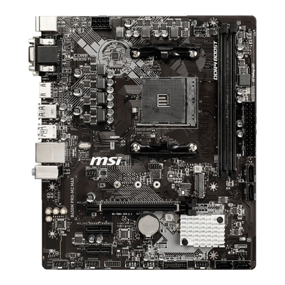
Thank you for purchasing the MSI
motherboard. This User Guide gives information about
board layout, component overview, BIOS setup and software
installation.
Contents
Safety Information ........................................................................................... 2
Specifications ................................................................................................... 3
Package contents............................................................................................. 6
Rear I/O Panel .................................................................................................. 7
LAN Port LED Status Table .................................................................................7
Overview of Components ................................................................................ 8
CPU Socket .........................................................................................................9
DIMM Slots ........................................................................................................10
PCI_E1~3: PCIe Expansion Slots ......................................................................10
JFP1, JFP2: Front Panel Connectors ...............................................................11
SATA1~4: SATA 6Gb/s Connectors....................................................................11
ATX_PWR1, CPU_PWR1: Power Connectors....................................................12
M2_1: M.2 Slot (Key M) .....................................................................................12
JUSB1~2: USB 2.0 Connectors .........................................................................13
JUSB3: USB 3.2 Gen1 Connector .....................................................................13
CPU_FAN1, SYS_FAN1: Fan Connectors ..........................................................14
JTPM1: TPM Module Connector .......................................................................15
JCI1: Chassis Intrusion Connector ...................................................................15
JAUD1: Front Audio Connector .........................................................................16
JCOM1: Serial Port Connector .........................................................................16
JLED1: LED strip connector .............................................................................16
JBAT1: Clear CMOS (Reset BIOS) Jumper .......................................................17
EZ Debug LED: Debug LED indicators ..............................................................17
BIOS Setup ..................................................................................................... 18
Entering BIOS Setup .........................................................................................18
Resetting BIOS ..................................................................................................19
Updating BIOS ...................................................................................................19
Software Description ..................................................................................... 20
Installing Drivers ..............................................................................................20
Installing Utilities ..............................................................................................20
10 .....................................................................................20
®
B450M PRO-M2 MAX
®
1
Contents
Advertisement
Table of Contents

Subscribe to Our Youtube Channel
Related Manuals for MSI B450M PRO-M2 MAX


Summary of Contents for MSI B450M PRO-M2 MAX
-
Page 1: Table Of Contents
B450M PRO-M2 MAX Thank you for purchasing the MSI ® motherboard. This User Guide gives information about board layout, component overview, BIOS setup and software installation. Contents Safety Information ................... 2 Specifications ....................3 Package contents..................... 6 Rear I/O Panel ....................7 LAN Port LED Status Table .................7... -
Page 2: Safety Information
Safety Information y The components included in this package are prone to damage from electrostatic discharge (ESD). Please adhere to the following instructions to ensure successful computer assembly. y Ensure that all components are securely connected. Loose connections may cause the computer to not recognize a component or fail to start. -
Page 3: Specifications
Memory y Supports ECC UDIMM memory (non-ECC mode) y Support non-ECC UDIMM memory * Please refer www.msi.com for more information on compatible memory. y 1 x PCIe 3.0 x16 slot (PCI_E1) ƒ Supports x16 speed with 1st, 2nd and 3rd Gen AMD Ryzen™... - Page 4 Continued from previous page y Realtek ALC887 Codec ® Audio y 7.1-Channel High Definition Audio 1x Realtek 8111H Gigabit LAN controller ® B450 Chipset ® y 2x USB 3.2 Gen1 (SuperSpeed USB) ports through the internal USB 3.2 Gen1 connector y 6x USB 2.0 (High-speed USB) ports (2 ports on the back panel, 4 ports available through the internal USB connectors) processor...
- Page 5 Multi-language y Drivers y APP MANAGER y SUPER CHARGER y COMMAND CENTER y LIVE UPDATE 6 y MYSTIC LIGHT Software y MSI SMART TOOL y X-BOOST y RAMDISK y Norton Security ™ y Google Chrome ,Google Toolbar, Google Drive ™...
-
Page 6: Package Contents
Continued from previous page y Audio ƒ Audio Boost y Storage ƒ Turbo M.2 ƒ StoreMI y Fan ƒ Smart Fan Control y LED ƒ Mystic light SYNC ƒ EZ DEBUG LED y Protection Special Features ƒ PCI-E Steel Slot y Performance ƒ... -
Page 7: Rear I/O Panel
Rear I/O Panel Line-in Line-out PS/2 Mouse USB 2.0 DVI-D Mic in USB 3.2 Gen1 PS/2 Keyboard LAN Port LED Status Table Link/ Activity LED Speed LED Status Description Status Description No link 10 Mbps connection Yellow Linked Green 100 Mbps connection Blinking Data activity Orange... -
Page 8: Overview Of Components
Overview of Components DIMMA1 CPU_PWR1 CPU_FAN1 DIMMB1 SYS_FAN1 CPU Socket EZ Debug LED 52.00mm* ATX_PWR1 SATA4 SATA3 M2_1 PCI_E1 JCI1 PCI_E2 BAT1 JBAT1 PCI_E3 JFP2 JAUD1 SATA2 SATA1 JCOM1 JFP1 JLED1 JUSB3 JUSB1 JTPM1 JUSB2 * Distance from the center of the CPU to the nearest DIMM slot. Overview of Components... -
Page 9: Cpu Socket
CPU Socket Please install the CPU into the CPU socket as shown below. Important When changing the processor, the system configuration could be cleared and reset BIOS to default values due to the AM4 processor’ s architecture. Always unplug the power cord from the power outlet before installing or removing the CPU. -
Page 10: Dimm Slots
If you install a large and heavy graphics card, you need to use a tool such as MSI Gaming Series Graphics Card Bolster to support its weight to prevent deformation of the slot. -
Page 11: Jfp1, Jfp2: Front Panel Connectors
JFP1, JFP2: Front Panel Connectors These connectors connect to the switches and LEDs on the front panel. HDD LED + Power LED + Power LED Power Switch HDD LED - Power LED - Reset Switch Power Switch JFP1 Reserved Reset Switch Power Switch HDD LED Reset Switch... -
Page 12: Atx_Pwr1, Cpu_Pwr1: Power Connectors
ATX_PWR1, CPU_PWR1: Power Connectors These connectors allow you to connect an ATX power supply. +3.3V +3.3V +3.3V -12V Ground Ground PS-ON# Ground Ground Ground ATX_PWR1 Ground Ground PWR OK 5VSB +12V +12V +3.3V Ground Ground +12V Ground +12V CPU_PWR1 Ground +12V Ground +12V... -
Page 13: Jusb1~2: Usb 2.0 Connectors
JUSB1~2: USB 2.0 Connectors These connectors allow you to connect USB 2.0 ports on the front panel. USB0- USB1- USB0+ USB1+ Ground Ground No Pin Important Note that the VCC and Ground pins must be connected correctly to avoid possible damage. -
Page 14: Cpu_Fan1, Sys_Fan1: Fan Connectors
CPU_FAN1, SYS_FAN1: Fan Connectors Fan connectors can be classified as PWM (Pulse Width Modulation) Mode or DC Mode. PWM Mode fan connectors provide constant 12V output and adjust fan speed with speed control signal. DC Mode fan connectors control fan speed by changing voltage. -
Page 15: Jtpm1: Tpm Module Connector
JTPM1: TPM Module Connector This connector is for TPM (Trusted Platform Module). Please refer to the TPM security platform manual for more details and usages. LPC Clock 3V Standby power LPC Reset 3.3V Power LPC address & data pin0 Serial IRQ LPC address &... -
Page 16: Jaud1: Front Audio Connector
JAUD1: Front Audio Connector This connector allow you to connect audio jacks on the front panel. MIC L Ground MIC R Head Phone R MIC Detection SENSE_SEND No Pin Head Phone L Head Phone Detection JCOM1: Serial Port Connector These connectors allow you to connect the optional serial port with bracket. SOUT Ground No Pin... -
Page 17: Jbat1: Clear Cmos (Reset Bios) Jumper
JBAT1: Clear CMOS (Reset BIOS) Jumper There is CMOS memory onboard that is external powered from a battery located on the motherboard to save system configuration data. If you want to clear the system configuration, set the jumper to clear the CMOS memory. Keep Data Clear CMOS/ Reset (default) -
Page 18: Bios Setup
BIOS Setup The default settings offer the optimal performance for system stability in normal conditions. You should always keep the default settings to avoid possible system damage or failure booting unless you are familiar with BIOS. Important BIOS items are continuous update for better system performance. Therefore, the description may be slightly different from the latest BIOS and should be held for reference only. -
Page 19: Resetting Bios
Updating BIOS Updating BIOS with M-FLASH Before updating: Please download the latest BIOS file that matches your motherboard model from MSI website. And then save the BIOS file into the USB flash drive. Updating BIOS: 1. Press Del key to enter the BIOS Setup during POST. -
Page 20: Software Description
Software Description Please download and update the latest utilities and drivers at www.msi.com Installing Windows ® 1. Power on the computer. 2. Insert the Windows 10 installation disc/USB into your computer. ® 3. Press the Restart button on the computer case.
Need help?
Do you have a question about the B450M PRO-M2 MAX and is the answer not in the manual?
Questions and answers