Table of Contents
Advertisement
Quick Links
Advertisement
Table of Contents

Related Manuals for Atlas Equipment LR-06P


Summary of Contents for Atlas Equipment LR-06P
- Page 1 Replace This With Cover PDF...
- Page 2 Revised: 9/04/2020 Read this entire manual before operation begins. Record below the following information which is located on the serial number data plate. Serial No. Model No. Date of Installation...
-
Page 3: Table Of Contents
Contents General Information..5 Product Identifi cation ..8 Packing, Transport, Storage ..9 Product Description ..10 Technical Specifi... - Page 4 for motor vehicles to the lift BOLD Important information TYPE WARNING: before operating the lift and carrying out any adjustment, read carefully chapter 7 “installation” where all proper operations for a better functioning of the lift are shown. LR-06P...
-
Page 5: General Information
• Any use of the machine made by operators who are not familiar with the instructions and procedures contained herein shall be forbidden. This manual is an integral part of the lift: it shall be given to the new owner if and when the lift is resold. LR-06P General Information... - Page 6 If the packing is not polluting or non-biodegradable, deliver them to appropriate handling station. General Information LR-06P...
- Page 7 The manufacturer is not liable for any mistakes made when drawing up this manual and reserves the right to make any changes due the development of the product, at any time. LR-06P General Information...
-
Page 8: Product Identifi Cation
Dealer where the machine has been bought or the Manufacturer’s Commercial Department. Only skilled personnel who are familiar with the lift and this manual shall be allowed to carry out packing, lifting, handling, transport and unpacking operations. Product Identification LR-06P... -
Page 9: Packing, Transport, Storage
Packages must be opened paying attention not to cause damage to people (keep a safe distance when opening straps) and parts of the lift (be careful the objects do not drop from the package when opening). Packing, Transport, Storage LR-06P... -
Page 10: Product Description
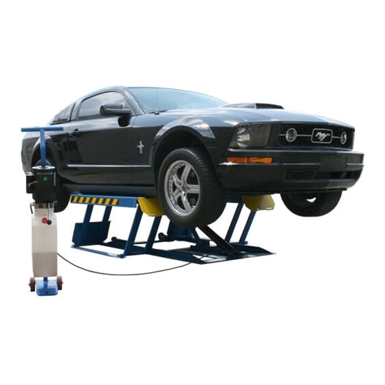
The lifting and lowering motion is carried out by operation of the lifting button and the lowering lever on the control unit (7). The mechanical safety (8) can be engaged and released automatically according to the lock in different position. Figure 1 – Lift Product Description LR-06P... -
Page 11: Technical Specifi Cation
If there is over 10% fl uctuation on the electrical power supply, it is suggested to use the voltage stabilizer to protect the electrical components and system from overloading. Technical Specification LR-06P... - Page 12 Pump Type Gear Flow rate 0.89 cm Continuous working pressure 200 bar – 220bar Figure 2 - Layout Technical Specification LR-06P...
- Page 13 Hydraulic Power Unit Figure 3 – Hydraulic Power Unit Technical Specification LR-06P...
- Page 14 Figure 4 – Hydraulic Plan Hydraulic cylinder Oil fi lter Flow restrictor Motor Non return valve Manual lowering valve Maximum pressure valve Starting valve Gear pump Technical Specification LR-06P...
- Page 15 Figure 5 – Electrical Wiring Diagram (110V/60Hz/1PH) Technical Specification LR-06P...
-
Page 16: Safety
• Be sure the motor of the vehicle is off, the gear engaged and the parking brake put on; • Be sure only authorized vehicles are lifted without exceeding the maximum lifting capacity; • Verify that no one is on the platforms during lifting or standing. Safety LR-06P... - Page 17 The operator must be sure no one is in danger before operating the lift. Fig. 6a Fig. 6b Fig. 6c Bumping Risk When the lift is stopped at relatively low height for working, the risk of bumping against projecting parts occurs. Fig. 7 Safety LR-06P...
- Page 18 Avoid use of water, steam, and solvent, varnish jets in the lift area where electric cables are placed and, in particular, next to the electric panel. Risks Resulting From Improper Lighting Make sure all areas next to the lift are well and uniformly lit, according to local regulations. Safety LR-06P...
- Page 19 Fig. 11 Any use of the lift other than that herein specifi ed can cause serious accidents to people in close proximity of the machine. Safety LR-06P...
-
Page 20: Installation
The surface must be suitable for bearing maximum stress values, also in unfavorable working conditions. The surface must be perfectly leveled. Hydraulic System Connection • Connect hydraulic hoses referring to the fi gure 12; Fig. 12 • Tighten fi ttings thoroughly. Hydraulic Connections Installation LR-06P... - Page 21 DO NOT continue pressing button after lift reaches full height. Damage to motor can occur if continued. • Lower the lift completely by pressing the lowering lever. • Repeat raise and lower the lift completely at least 5 times to remove the air. Installation LR-06P...
- Page 22 WARNING: please follow carefully the instructions in the coming paragraph for avoiding damages on the lift. Carry out two or three complete cycles of lowering and lifting and check: • Repeat the 7.7 section. • Check no strange noise during lifting and lowering. Installation LR-06P...
-
Page 23: Operation And Use
• Press the lifting button till the lift is raised to the required height and the locks are in engaged position (see Fig.15), then press the lowering lever to lower the lift to engage the mechanical safety. Operation And Use LR-06P... - Page 24 • Pull up the roller bracket, lock two roller assemblies on the lift with roller shaft. • Be sure the roller assembly must be engaged when moving vehicle (see Fig. 17). • Move the lift by the trolley’s hook. Fig.17 Operation And Use LR-06P...
-
Page 25: Maintenance
The use of water or infl ammable liquid is strictly forbidden. Be sure the rod of the hydraulic cylinders is always clean and not damaged since this may result in leakage from seals and, as a consequence, in possible malfunctions. Maintenance LR-06P... - Page 26 • a check of the electrical system to verify Electrical Every 12 months that motor, must be carried out by skilled system electricians • empty the oil tank and change the hydraulic oil Maintenance LR-06P...
-
Page 27: Troubleshooting
Bleed the hydraulic system into hydraulic circuit The lift does not lift or lower The pump fi lter is dirty Check and clean if needed smoothly Check the seal and replace if The pump suction is blown needed Troubleshooting LR-06P... -
Page 28: Parts List
Parts List Lift Lift Item Part No. Description J52B200100 Lifting arm J52B000005 Pin shaft J52B000100 Ramp J52B100000 Base J52B000002 Lower shaft J52BY75000 Hydraulic cylinder 0212004 Seeger D.25 - GB/T894.1 0202063 Screw M10X35 - GB/T70.1 J52B000006 Lock latch Parts List LR-06P... - Page 29 Self-locking nut M10 J52B000200 Lock arm J52B300000 Platform J52B00003 Upper shaft 0206092 Screw M6X12 - GB/T70.2 J44A000002 Rubber pad 14X110X431 0212016 Seeger D.18 - GB/T894.1 J52B200200 Arm ramp J52B000004 J52B000001 7630A-03000 Power unit frame 0302021 Hydraulic power unit Parts List LR-06P...
- Page 30 Part No. Description J52B100003 Spring 0205011 Washer D.10 - GB/T97.1 0204005 Self-locking nut M10 J52B120100 Roller support J52B100002 J52B100001 Roller shaft 0511122 WHEEL 4” 0212001 Seeger D.12 0201057 Screw M10X120 - GB/T5782 J52B120200 Roller support J52B110100 Base support Parts List LR-06P...
- Page 31 Split pin 2X20 - GB/T91 0511122 Wheel 7630A-03200 Handle 0205008 Washer D.8 - GB/T97.1 0208007 Locking washer D.10 - GB/T93 0205011 Washer D.10 - GB/T97.1 0205013 Washer D.12 - GB/T97.1 0603007 Cover 0201064 Screw M10X25 - GB/T5783 Parts List LR-06P...
- Page 32 J44AY75002 Cylinder guiding cover 0202122 Screw M16X30 - GB/T70.1 0305007 Guiding ring 70X10X2.5 0305007 Guiding ring 40X10X2.5 0311008 Scraper 40X48X5 0309039 O-ring 75X3.1 0309100 O-ring 40X3.55 0310038 Seal 65X75X6 0313066 Ring75X65X2.5 J52BY75100 Cylinder liner J52BY75200 Cylinder shaft Parts List LR-06P...
-
Page 33: Warranty
Prices do not include any local, state or federal taxes. RETURNS: Products may not be returned without prior written approval from the Manufacturer. DUE TO THE COMPETITIVENESS OF THE SELLING PRICE OF THESE LIFTS, THIS WARRANTY POLICY WILL BE STRICTLY ADMINISTERED AND ADHERED TO. Warranty LR-06P...
Need help?
Do you have a question about the LR-06P and is the answer not in the manual?
Questions and answers