Table of Contents
Advertisement
Quick Links
PowerHold
®
Vehicle Restraint
Owner's/User's Manual
Poweramp • Division of Systems, LLC • W194 N11481 McCormick Drive • Germantown, WI 53022
800.643.5424 • fax: 262.255.5917 • www.poweramp.com • techservices@poweramp.com
Printed in U.S.A.
Manual No. 4111-0016
© 2019 Systems, LLC - All Rights Reserved
Aug. 2019
Advertisement
Table of Contents
Troubleshooting

Summary of Contents for SYSTEMS Poweramp PowerHold
- Page 1 PowerHold ® Vehicle Restraint Owner’s/User’s Manual Poweramp • Division of Systems, LLC • W194 N11481 McCormick Drive • Germantown, WI 53022 800.643.5424 • fax: 262.255.5917 • www.poweramp.com • techservices@poweramp.com Printed in U.S.A. Manual No. 4111-0016 © 2019 Systems, LLC - All Rights Reserved...
-
Page 2: Table Of Contents
Table of Contents Page Page Precautions Maintenance Recognize Precautionary Information .....1 Maintenance Precautions ........25 General Operational Precautions ......1 Periodic Maintenance ..........26 Operational Precautions ...........2 Adjustments Safety Decals .............4 Placard................5 PowerHold Dry Cycle ..........28 Owner’s/User’s Responsibilities ......6 Prox Switch Adjustments ........29 Adjust Dock Leveler and Vehicle Restraint Introduction Interlock.............. -
Page 3: Precautions
WARNING: This product can expose you to chemicals including lead, which are known to the State of California to cause cancer or birth defects or other reproductive harm. For more information go to www.P65Warnings.ca.gov 4111-0016 — Aug. 2019 © 2019 Systems, LLC... -
Page 4: Operational Precautions
Keep hands and feet clear of pinch points. Avoid putting any part of your body near moving parts. Make sure lip overlaps onto transport vehicle bed at least 4 in. (102 mm). Keep a safe distance from both side edges. 4111-0016 — Aug. 2019 © 2019 Systems, LLC... - Page 5 Do not overload the dock leveling device. Do not operate any equipment while under the influence of alcohol or drugs. Do not leave equipment or material unattended on dock leveling device. 4111-0016 — Aug. 2019 © 2019 Systems, LLC...
-
Page 6: Safety Decals
Decal Placement for H Series Figure 2 Note: This is a example of dock leveler safety decals. See specific model manual for correct safety decal sheet, or consult Systems, LLC Tech Services. 4111-0016 — Aug. 2019 © 2019 Systems, LLC... -
Page 7: Placard
Call for additional placards, or manuals, or with questions regarding proper use, maintenance, and repair of dock leveler. WARNING: CANCER AND REPRODUCTIVE HARM 1751-0880 Rev F Use for PowerHook, PowerHold, HoldTite and TPR series www.P65Warnings.ca.gov 1751-0880 4111-0016 — Aug. 2019 © 2019 Systems, LLC... -
Page 8: Owner's/User's Responsibilities
Contact manufacturer for any wheel chocks shall be engaged. Also, whenever replacements. possible, air-ride suspension systems should have the air exhausted prior to performing said 5) Modifications or alterations of restraining devices loading and unloading operations. - Page 9 11) Restraining devices that are structurally damaged shall be removed from service, inspected by a manufacturer’s authorized representative, and repaired or replaced as needed or recommended by the manufacturer before being placed back in service. 4111-0016 — Aug. 2019 © 2019 Systems, LLC...
-
Page 10: Introduction
To illustrate which connections are to be made in the field at installation, electrical drawings are included The vehicle restraint is firmly anchored to the drive with each order or by contacting Systems, LLC way approach or the building wall for maximum Technical Services. -
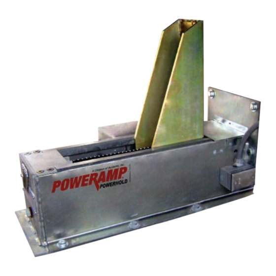
Page 11: Component Identification
G R E E O N L Y Figure 4 A — PowerHold Assembly* C — Outside Light Assembly B — Control Box* D — Outside Signs *Appearance may vary depending on options. 4111-0016 — Aug. 2019 © 2019 Systems, LLC... - Page 12 D — Pressure to Logic Block G — Return to Logic Block B —Solenoid Coil E — Pressure to Restraint H— Pressure from Pump C —Diverter Valve F — Return from Restraint I — Return to Pump 4111-0016 — Aug. 2019 © 2019 Systems, LLC...
- Page 13 INTRODUCTION This page intentionally left blank. 4111-0016 — Aug. 2019 © 2019 Systems, LLC...
-
Page 14: Installation
Always keep a fire extinguisher of the proper type nearby when grinding or welding. Only trained installation professionals with the proper equipment should install this product. 4111-0016 — Aug. 2019 © 2019 Systems, LLC... -
Page 15: Concrete Dock Face
4111-0016 — Aug. 2019 .000 = .005" ANGULAR: This print is the property of Systems, Inc. and repre © 2019 Systems, LLC patent and other rights, including exclusive rights of not convey any permission to reproduce, print or ma granted only by written authorization signed by an o... -
Page 16: Driveway Mount
MATERIAL IMBED WELDMENT - POWERS DRAWN BY CHECKED BY DRIVEWAY - MOUNTE 4111-0016 — Aug. 2019 TOLERANCES DRAWING NO. (UNLESS OTHERWISE NOTED) MATERIAL © 2019 Systems, LLC FRACTIONAL: 1/32" 7953-0 DECIMAL: DRAWN BY CHECKED BY .00 = .01" .000 = .005"... -
Page 17: Cantilevered Dock
+ Dim. B Note: Walls must be poured concrete, 8” thick minimum to install with wedge anchors. Concrete block or brick is not acceptable. Dim. A Dim. B Offset Required Figure 16 4111-0016 — Aug. 2019 © 2019 Systems, LLC... -
Page 18: Remote Powerpack Location Options
3” PVC (hydraulic) and 3/4” conduit (electrical) chase during pit construction. Note: Figure 19 is provided as an example only; specific routing may differ depending on leveler configuration. Figure 19 4111-0016 — Aug. 2019 © 2019 Systems, LLC... - Page 19 .005" ANGULAR: This print is the property of Systems, LLC and r of use and/or manufacture and/or sale. Posses such permission to be granted only by written a Figure 20 4111-0016 — Aug. 2019 © 2019 Systems, LLC...
-
Page 20: Install Control Panel And Wiring
If the conduit could fill with water, a drip leg may contain more than one power source. may be needed. Hazardous Voltage Will Result in Death 6. Install Outside Light Assembly and signs (see or Serious Injury Figure 22). 4111-0016 — Aug. 2019 © 2019 Systems, LLC... -
Page 21: Install Outside Light Assembly And Signs
ONLY” signs on outside of building above and below should always be run to ensure correct operation. Outside Light Assembly. 4. Install “CAUTION: ENTER ON GREEN ONLY” sign inside building near control box. 5. Install placard (see page 20). 4111-0016 — Aug. 2019 © 2019 Systems, LLC... -
Page 22: Placard Installation Instructions
(Placard placement shown as reference Nylon Tie (Placard placement only.) shown as reference Conduit only.) Conduit A - Control Box B - Placard C - Nylon Cable Tie D - Conduit Figure 23 4111-0016 — Aug. 2019 © 2019 Systems, LLC... - Page 23 INSTALLATION This page intentionally left blank. 4111-0016 — Aug. 2019 © 2019 Systems, LLC...
-
Page 24: Operation
Rear Impact Guard (RIG) bar. Proper engagement occurs when the shoe is standing vertically, contacting the front edge of the horizontal member of the RIG, without obstruction. 4111-0016 — Aug. 2019 © 2019 Systems, LLC... -
Page 25: Operation - Bypass
Or, to reset back to NORMAL mode, press RELEASE button. • Inside light - GREEN • Outside light - RED See the iDock Owner’s/User’s Manual for more information on iDock menus and navigation. 4111-0016 — Aug. 2019 © 2019 Systems, LLC... -
Page 26: Multi-Colored & Outside Light Sequence Charts
Reset Lights to Normal Mode Red, Display Backlight (5 seconds) Green Menu & Diagnostics Lights Condition Inside Outside Main Menu Active Red (solid) Red (solid) System Fault Present Red/Amber Restraint Use Disabled Amber None 4111-0016 — Aug. 2019 © 2019 Systems, LLC... -
Page 27: Maintenance
Always stand clear of platform lip when working in complete. front of the dock leveler. * Refer to OSHA regulations 1910.146. Confined Space and 1910.147. Lockout/Tagout 4111-0016 — Aug. 2019 © 2019 Systems, LLC... -
Page 28: Periodic Maintenance
This print is the property of Systems, LLC and represents a proprietary article in which Systems, LLC retains any and all patent and other rights, including exclusive rights of use and/or manufacture and/or sale. Possession of this print does not convey any permission to reproduce, print or manufacture the article or articles shown therein, such permission to be granted only by written authorization signed by an officer or other authorized agent of Systems, LLC thereof. - Page 29 F — Breather Cap 6. Install breather cap and cover plate (SC models). 7. Turn ON electrical power to the restraint. 8. Operate the PowerHold vehicle restraint through the complete operating cycle to verify operation. 4111-0016 — Aug. 2019 © 2019 Systems, LLC...
-
Page 30: Adjustments
ENTER button (user code may be required). Or, to reset back to NORMAL mode, press RELEASE button. See the iDock Owner’s/User’s Manual for more information on iDock menus and navigation. Operating range is NOT adjustable. 4111-0016 — Aug. 2019 © 2019 Systems, LLC... -
Page 31: Prox Switch Adjustments
(CCW) 1/2 turn until switch is no longer flush with the latch block. Make sure that the wiring from the prox switches are clear of all moving parts. 4111-0016 — Aug. 2019 © 2019 Systems, LLC... -
Page 32: Adjust Dock Leveler And Vehicle Restraint Interlock
Pressing the restraint RELEASE button when in BYPASS mode will return the leveler to NORMAL operating mode. Special interlocking options are available upon request. Call Systems, LLC to discuss interlock options to meet your specific needs. *Dock levelers equipped with Auto-Return-To-Dock have limited interlocking options. Auto-Return-... - Page 33 This print is the property of Systems, LLC and represents a proprietary article in which Systems, LLC retains any and all patent and other righ to the operator. (B) so that the target is not in the sensing range of of use and/or manufacture and/or sale.
-
Page 34: Troubleshooting
6. The shoe will then rotate down to the stored maintenance is complete. position. 4111-0016 — Aug. 2019 © 2019 Systems, LLC... -
Page 35: Troubleshooting
Check controller output that sends a signal to starter Motor starter (3 phase) or or relay. Output may have failed OPEN. Use meter motor relay (1 phase) not to check for contact closure when output ON. energizing. 4111-0016 — Aug. 2019 © 2019 Systems, LLC... - Page 36 Ensure pressure relief cartridge is adjusted per max PowerHold raises slowly, or amp draw. is slow to release. Damage or blocked Replace damaged hose(s). Check and remove hydraulic hose(s) and/or blockage from hose(s) and/or valve(s). valve(s). 4111-0016 — Aug. 2019 © 2019 Systems, LLC...
- Page 37 0.83 ft. lbs. (just over finger tight). Do not over-tighten valve into block. Max torque is 15 ft. lbs. which will compress O-ring and prevent leakage. Operate unit. Replace valve if problem persists after all other troubleshooting procedures. 4111-0016 — Aug. 2019 © 2019 Systems, LLC...
- Page 38 0.83 ft. lbs. (just over finger tight). Do not over-tighten valve into block. Max torque is 15 ft. lbs. which will compress O-ring and prevent leakage. Operate unit. Replace valve if problem persists after all other troubleshooting procedures. 4111-0016 — Aug. 2019 © 2019 Systems, LLC...
- Page 39 Restraint timed out because of faulty stored prox switch. Check for damaged switch or wire connections. If additional troubleshooting assistance is required, contact Systems, LLC Technical Services with equipment serial number or customer order number (CO#). Technical Service at 800-643-5424 or techservices@loadingdocksystems.com 4111-0016 —...
-
Page 40: Parts
PARTS PowerHold Assembly 4111-0016 — Aug. 2019 © 2019 Systems, LLC... - Page 41 Screw, Allen Head 1/2-20 UNC x 1-1/2 Lg. 9414-0074 Base Weldment 8581-0137 One-Way Check Valve 2101-0153 Hex Head Cap Screw, Zinc Plated, 1/4”-20 UNC x 1/2” *Provide vehicle restraint serial number when e-mailing, calling or faxing orders. 4111-0016 — Aug. 2019 © 2019 Systems, LLC...
-
Page 42: Powerhold Sc Valve Block
This print is the property of Systems, Inc. and represents a proprietary article in which Systems, Inc. retains any and all This print is the property of Systems, Inc. and represents a proprietary article in which Systems, Inc. retains any and all patent and other rights, including exclusive rights of use and/or manufacture and/or sale. -
Page 43: Powerhold And Leveler Combination Valve Block
Fitting Elbow 90 Deg STR Thread #6 ORB x #8 JIC 9301-0116 Fitting Elbow 90 Deg STR Thread #8 ORB x #8 JIC 8581-0004 Coil, Delta 4301-0001 Cable Assembly 48” Lg *Provide vehicle restraint serial number when e-mailing, calling or faxing orders. 4111-0016 — Aug. 2019 © 2019 Systems, LLC... -
Page 44: Powerhold Latch Assembly
Stored Prox Switch 0941-0008 Spring 0941-0009 Spring 2101-0012 Bolt 5/16-18 UNC 2101-0058 Nut, Hex 5/16-18 UNC 9414-0081 Latch Assembly (Complete With Prox Switches) *Provide vehicle restraint serial number when e-mailing, calling or faxing orders. 4111-0016 — Aug. 2019 © 2019 Systems, LLC... -
Page 45: Powerhold Sc Powerpack
Hex Head Cap Screw, Zinc Plated, 1/4”-20 UNC x 1/2” 3411-0049* Motor, SC, 8/2012-present, 6.8FLA *Provide vehicle restraint serial number when e-mailing, calling or faxing orders. Contact Tech Services for pre-8/2012 units. 4111-0016 — Aug. 2019 © 2019 Systems, LLC... -
Page 46: Remote Mount Powerpack Assembly
.000 = Restraint pressure is set by relief valve on restraint. ANGULAR: This print is the pro of use and/or manu such permission to Remote mount powerpack pressure is factory set. 4111-0016 — Aug. 2019 © 2019 Systems, LLC... - Page 47 Cable, 5M Lg, M12 Plug (Optional) Provide dock leveler serial number and type of installation when e-mailing, calling or faxing orders. Provide dock leveler serial number, voltage, and phase when e-mailing, calling or faxing orders. 4111-0016 — Aug. 2019 © 2019 Systems, LLC...
-
Page 48: Filler Kits
FORMED, ZINC PLATED 9416-0003 Filler Kit, Hold Restraint, Formed, Zinc Plated (2”-14” projection)* *Must specify required filler projection when e-mailing, calling or faxing orders. MATERIAL STOCK NO. 4111-0016 — Aug. 2019 DRAWN BY CHECKED BY DATE © 2019 Systems, LLC 3/30/2018... -
Page 49: Osla (Outside Light Assembly)
Green LED Lens/Housing/Circuit Assembly, 12v granted o 3051-0068 Mounting Gasket 3051-0105 Clip, Lens Holding 3051-0104 Screw, Lens Holding Conduit Fastener, 3/4” x 3/8” *Provide vehicle restraint serial number when e-mailing, calling or faxing orders. 4111-0016 — Aug. 2019 © 2019 Systems, LLC... -
Page 50: Signs
IN OR OUT ON OUT ON GREEN GREEN ONLY ONLY Germantown, WI 53022 Germantown, WI 53022 Item Part Number Description 1751-0033 Outside Sign, Pull In/Out 1751-0034 Outside Sign, Pull In/Out (Mirror Image) 4111-0016 — Aug. 2019 © 2019 Systems, LLC... -
Page 51: Miscellaneous
(A, B) becomes lost or damaged. Vehicle Restraint Information Also, write down Systems, LLC’s order number, the Model ___________________________________ company that installed the equipment, and the original owner’s name. This will all help to identify the specific Serial No. -
Page 52: Warranty
Owner/User. In the event of a defect, as determined by SYSTEMS LLC, covered by this warranty, SYSTEMS LLC shall remedy such defect by repairing or replacing any defective equipment or parts, bearing the cost for the parts, labor and transportation.
Need help?
Do you have a question about the Poweramp PowerHold and is the answer not in the manual?
Questions and answers