Table of Contents
Advertisement
Quick Links
Manual
– Precision Water Level Instruments – Model 6541
Revision History
File name / Revision
Previous version BX
Unidata Manual - 6541 Precision Water Level Instruments Issue 2.1
Copyright © Unidata Pty Ltd 2000-2008. All rights reserved. No part of this publication may be reproduced, transmitted,
transcribed, stored in a retrieval system, or translated into any spoken or computer language, in any form or by any means.
Electronic, mechanical, magnetic, optical, chemical, manual or otherwise, without prior written permission of Unidata Pty Ltd 40
Ladner St, O'Connor Western Australia 6163.
Unidata Manual - 6541 Precision Water Level Instruments Issue 2.1
Manual
Precision Water Level Instruments
Model 6541
Date
Authors
2004
RS/ JH
2007
AB/CB/JH/MS/KC
Advertisement
Table of Contents

Related Manuals for UniData Communication Systems 6541


Summary of Contents for UniData Communication Systems 6541
- Page 1 Authors Previous version BX 2004 RS/ JH Unidata Manual - 6541 Precision Water Level Instruments Issue 2.1 2007 AB/CB/JH/MS/KC Copyright © Unidata Pty Ltd 2000-2008. All rights reserved. No part of this publication may be reproduced, transmitted, transcribed, stored in a retrieval system, or translated into any spoken or computer language, in any form or by any means.
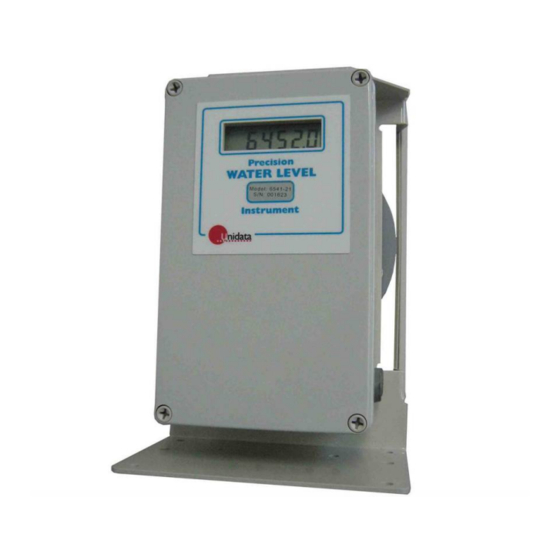
- Page 2 Manual – Precision Water Level Instrument Picture of the Water Level Instrument Unidata Manual 6293 - Precision Water Level Instruments Issue 2.1...
-
Page 3: Table Of Contents
........22 NSTALLING THE NSTRUMENT IN THE ECORDING OSITION ................22 NSTALLING THE LOAT YSTEM ..............23 ETTING THE NSTRUMENT ATERLEVEL 6541 APPLICATIONS....................24 ..............24 EASURING URFACE ATER EVELS ..............24 EASURING LOW IN HANNELS ..............24 EASURING ROUND... - Page 4 EVEL EASUREMENT ..............26 OURCES OF RROR IN LOAT YSTEMS ....................27 AUSES OF RROR SPECIFICATIONS: MODEL 6541 INSTRUMENT ..........28 APPENDIX A - 6541L MICROLOGGER..............29 ......................29 PECIFICATIONS ........................ 29 OUNTING ....................30 IGNAL ONNECTIONS ....................31 THER ONNECTORS (UPS)................
-
Page 5: 6541B Water Level Instrument
Throughout this manual the model number 6541 will be used when describing features common to all the 6541 family of instruments. When describing features specific to an individual model of the 6541 family, the model number will be used. For example: 6541B-11-C. -
Page 6: Applications
Using the 6541 The 6541 is simple to install and use. At installation all adjustments are made using the switches located inside the front cover. Each instrument has a LCD display that shows the water level reading and updates automatically as the water level changes. -
Page 7: Features
Precision Water Level Instrument Features Most wiring connections to the 6541B Water Level Instrument are made by the front panel screw terminals. Power Supply. The instrument can be powered either from a Unidata battery pack plug or, via flying leads from an external power source. HSIO. -
Page 8: Operating Modes
With an Internal Data Logger - As a water level measurement and display instrument with a built-in data logger – the 6541-nnn/C that can measure up to three additional external parameters. With an External Data Logger - As a water level measurement and display instrument, with an external data acquisition facility such as a UNIDATA STARLOGGER. -
Page 9: Models
Precision Water Level Instrument Models The Model 6541 Instrument can be supplied in a number of versions to suit different applications. Versions are indicated by a three digit code appended to the instrument model number. The example below shows the instrument with: A 500mm pulley, alkaline battery and UNIDATA Micrologger fitted. -
Page 10: Model 6541B With Micrologger
UNIDATA Model 6541B with Micrologger To specify the internal Micrologger, add -C to the 6541B version you select. Output Options The instrument has three output interface options: SDI-12 Interface. The 6541B Water Level Instrument has a Version 1.3 - compliant SDI-12 sensor interface. -
Page 11: Mounting And Installation Options
Available mounting options help simplify your installation and adapt the instrument to different applications. Mounting Adapter Plates These can be bolted to the base to allow the 6541 to mount on the same holes as the superseded 6509. Offset Pulley These attach to the instrument mounting bracket to guide the float line to hang correctly inside the float well. -
Page 12: Micrologger Options
The 6541L Micrologger also includes one open collector output that can control an external device. You should use the 6541-nn-C when you need to measure water level and a couple of other physical parameters. The 6541B-L Micrologger is program-compatible with UNIDATA data loggers. -
Page 13: Logging Data
Precision Water Level Instrument 3 LOGGING DATA With the 6541 Precision Water Level Instrument connected to a STARLOGGER or PROLOGGER or, when using the 6541-nn-C internal Micrologger; the water level sensed by the instrument is logged and stored according to a data logging program (called a Scheme), defined within the STARLOG Software Package. - Page 14 If you choose to log data via a channel other than the default (channel S0), ensure the 6541 is connected to the correct terminal on the Field Termination Strip if you are using one, or the correct pin in the INPUT SIGNALS connector if you are connecting directly to a STARLOGGER.
-
Page 15: When To Log
The logger will read the 6541 at the scan intervals you select. You have the option of time based logging (e.g. each 15 minutes), event based logging (e.g. -
Page 16: What To Log
UNIDATA Scan rate. • Log interval. • Log sub-interval. • The scan rate defines the frequency at which the logger “wakes-up” and interrogates the instrument. This is typically 5 seconds, however a shorter interval may be defined for better data definition or, a longer interval to conserve data logger battery power. - Page 17 Precision Water Level Instrument The data from the last scan (RAW), The average of some (ave) or all (AVE) scans or, The maximum (MAX) or, The minimum (MIN) scan For example, with a time based scheme you may want to log the average value of all scans, and also the maximum during each log period.
-
Page 18: Preparing For Installation
Controls and Settings All the controls you need to install and operate the 6541 are accessed by removing the front cover. The factory default switch settings are: Display counts up. -
Page 19: Connecting To An External Data Logger Via Hsio
Precision Water Level Instrument Connecting to an External Data Logger via HSIO Removing the front cover reveals a termination block to which the data logger cable is connected. This cable exits through the gland in the side of the instrument. External power may be connected to the designated terminals. -
Page 20: Hsio Interfaces
UNIDATA 4.3.1 HSIO Interfaces. The 6541B has two HSIO interfaces. The primary interface is accessible via the screw terminals at the front of the instrument. The secondary HSIO interface is accessed by the IDC header located low on the rear of the PCB and is intended for connection to a Micrologger. -
Page 21: Wiring Connections
Precision Water Level Instrument The CRCed version of this command is also valid. Note the valid addresses for the 6541B instrument are (ASCII) 0 z inclusive. The address of the instrument is set to a default value of 0 at delivery. 4.5.1 Wiring Connections Terminal 8 SDI-12 Signal Terminal 7 SDI-12 GND... -
Page 22: Current Loop Interface (4-20Ma)
UNIDATA In the commands: • “a” is the sensor address. • “!” terminates the command. • “<CR><LF>” terminates the response from the instrument. When requested via sdi-12 the 6541B will return the water level value shown on the LCD. The returned ASCII string will exclude any leading zeros. The exception to this is where the display has a 0 to the left of the decimal point. -
Page 23: Span & Zero Configuration
Precision Water Level Instrument 4.6.2 Span & Zero Configuration. The “zero” value is the level for I = 4mA. The “span” value is the level for I = 20mA. To save power the 6541B zero & span values can be transposed providing a 20/4mA output. -
Page 24: Hsio Interfaces
UNIDATA HSIO Interfaces. The 6541B has two HSIO interfaces. The primary interface is accessible via the screw terminals at the front of the instrument. The secondary HSIO interface is accessed by the IDC header located low on the rear of the PCB and is intended for connection to a Micrologger. -
Page 25: Bench Testing The Instrument System
Precision Water Level Instrument Bench Testing the Instrument System If practical, assemble the equipment in the housings and on the mounting you will be using at the field site. This will ensure you have everything you need. When you have connected the instrument to the logger and selected the correct settings, you load the scheme into the logger. -
Page 26: Site Installation
UNIDATA 5 SITE INSTALLATION The site should be constructed according to the instructions in the relevant appendices. Installation of the instrument at your measuring location is a simple process if the system has already been prepared and bench tested. It generally involves the following steps: •... -
Page 27: Setting The Instrument Waterlevel
Precision Water Level Instrument cable, turn the pulley to engage the index beads into the holes in the float pulley groove. Setting the Instrument Water Level To do this: 1. Remove the front cover of the instrument. 2. Set the battery switch (number 8) to the ON position. 3. -
Page 28: 6541 Applications
Measuring Surface Water Levels Water levels in lakes, reservoirs, tidal estuaries and process tanks are monitored for research and management. The 6541 mounted on a suitable floatwell will provide accurate and reliable data in these applications. Measuring Flow in Open Channels... -
Page 29: Floatwell Design For Water Level Measurement
Floatwell Design for Water Level Measurement A floatwell or stilling well is required at any site where a 6541 instrument is used. At many sites floatwells are simple devices that can be constructed from lightweight materials such as PVC pipe. On larger rivers constructing new floatwells can be uneconomic and alternative instruments such as UNIDATA Pressure transducers should be considered. -
Page 30: Measuring Pan Evaporation
Floatwell Design for Water Level Measurement A floatwell or stilling well is required at any site where a 6541 instrument is used. At many sites floatwells are simple devices that can be constructed from lightweight materials such as PVC pipe. On larger rivers constructing new floatwells can be uneconomic and alternative instruments such as UNIDATA Pressure transducers should be considered. -
Page 31: Causes Of Error
Precision Water Level Instrument proposed. Significant source of error can occur at sites such as reservoirs and bores where large variations in water level are recorded. When the float movement exceeds 10 metres, special components or designs may be required. This is because the net weight of the floatline transfers from one side of the pulley to the other. -
Page 32: Specifications: Model 6541 Instrument
UNIDATA 7 SPECIFICATIONS: MODEL 6541 INSTRUMENT Range: Standard 0 to 65535mm. Switch to 6553.5mm, 655.35’ or 655.35” to suit the float pulley used. Resolution: 1.0mm or 0.1mm, 0.01’ or .01”, depending on the range selected. Accuracy: 1 resolution increment, with suitable float system. -
Page 33: Appendix A - 6541L Micrologger
8 APPENDIX A - 6541L MICROLOGGER The 6541L is a variant of the UNIDATA Model 8007B Micrologger, designed to be used with Model 6541 Precision Water Level Instrument. The MicroLogger is program compatible with the STARLOGGER, supporting many of its extended features such as SDI-12 and HSIO communications. -
Page 34: Signal Connections
UNIDATA Signal Connections RS-232 DB-9 CONNECTOR Description Carrier Detect Receive Data Transmit Data Data Terminal Ready Ground Data Set Ready Request to Send Clear To Send Ring Indicator Signal Communication Terminals Pin Label Description Output Digital/Power Ground OUT0 Open Collector Control Output INP0 Digital Input (Log Start) Digital Power Ground... -
Page 35: Other Connectors
Precision Water Level Instrument Other Connectors There are two other connectors on the Micrologger PCB: 10 Way Header - alternative RS-232 port. The cable can be supplied for this • port. 14 Way Header - connects to the encoder PCB. •... -
Page 36: Register Allocation
UNIDATA Register Allocation The Model 6541L MicroLogger operating the standard instruction set has the following fixed memory assignments in the Hardware Register: Address Size Description Software Revision Number (20 onwards) Logger runtime in milliseconds (16 bit integer) Error flags Logger scan counter (32 bit integer) Reserved Reserved msb of address (bits 8-23) used in LDBLK and MVBLK... -
Page 37: Field Installation
Precision Water Level Instrument Field Installation Do the following: 1. Unscrew the lid of the 6541 and remove the battery pack. 2. Remove the four screws that secure the metal frame on which the PCB and LCD are mounted. 3. Remove the cable between the PCB and the instrument from the top of the instrument housing. -
Page 38: Appendix B - Details Of Unidata Float Systems
UNIDATA manufactures a range of float systems and accessories to suit the requirements of various customers. These products are available as options for the new 6541 Precision Water level Instrument. Each float is supplied with floatline swages and a 160g lead counterweight (epoxy painted). - Page 39 Weight: 1100g. Model 6541F-115 This float is suitable for sites where a 6541 is installed and the water level range is small, or a lightweight floatline is used. This float is designed for use in a floatwell with a minimum diameter of 150mm. The float has a cylindrical shape with a flat bottom for maximum sensitivity.
- Page 40 UNIDATA Model 6541F-90 (Previously 6509F) This float is suitable for sites with a small water level range or where a lightweight floatline is used. The float is designed for use in a floatwell with a minimum diameter of 125mm, or 100mm if a separate counterweight tube is used.
-
Page 41: Float Pulleys
Precision Water Level Instrument Float Pulleys Pulley Type Model Usage 500mm Metric 6541P/ Use with 1mm cable with circumference M500 optional beads each 125mm. 12” Imperial 6541P/I Use with 1mm cable with circumference optional beads each 3 inches. 100mm Metric 6541P/ Use with 0.4mm cable. -
Page 42: Appendix C - Float Systems
UNIDATA 10 APPENDIX C - FLOAT SYSTEMS 10.1 Introduction to Float Systems Float systems used for monitoring water level usually consist of a sealed float connected to a floatline that passes over a pulley on a measuring instrument. A counterweight is connected to the end of the floatline to maintain tension. The pulley over which the floatline passes is connected to a shaft. -
Page 43: Float Line Shift
Precision Water Level Instrument Instrument lag. • Temperature change. • These causes of error are discussed below: Other minor causes relate to water density and the movements of supporting structures and the expansion of such structures resulting from changes in temperature and water content. -
Page 44: Temperature Change
UNIDATA This error (caused by friction in the measuring apparatus) is not cumulative and is usually not very large. Formula 4 (on the following page) details the error caused by instrument lag. 10.3.4 Temperature Change Changes in temperature will cause the float line to expand and contract. The amount of expansion (contraction) is usually small and is often compensated by the simultaneous expansion (contraction) of the level instrument supporting structures. -
Page 45: Example
Precision Water Level Instrument length of line between instrument and float. Coefficient of expansion (X Factor). 10.3.7 Example A water level instrument has an 85mm diameter float, a beaded stainless steel cable and a 160gm counterweight (always above the float). What errors would occur if the level rose by 2 metres? (In this case we will ignore temperature changes as there is no information about the supporting structures). -
Page 46: Appendix D - Floatwells
UNIDATA 11 APPENDIX D – FLOATWELLS 11.1 The Need for Floatwells If a float is located on open water, it can be affected by waves, wind and water movement. If any of these influences are strong enough to interfere with the position of the float, inaccurate measurements will result. -
Page 47: Mounting The Instrument On A Floatwell
Precision Water Level Instrument To operate correctly, a floatwell must have the following features. It should: Have sufficient internal diameter to accommodate the float used with the • measuring instrument. Be long enough to allow the float system to move freely from the •... -
Page 48: Siltation
UNIDATA flowing, the larger the slope will be. The measuring location will need to be the point of interest as the varying slope will introduce different errors in different conditions. If the water velocity is too high, it can begin to affect the water level inside the floatwell by causing a venturi effect on the inlet holes. -
Page 49: Access And Security
Precision Water Level Instrument blend in with their environment. Channel changes and structures should be kept to a minimum. Access paths should be established in ways that minimise damage. Provision should be made for any structures to be removed and the site restored to its original condition when the measurement project is complete.
Need help?
Do you have a question about the 6541 and is the answer not in the manual?
Questions and answers