Table of Contents
Advertisement
Quick Links
Advertisement
Table of Contents

Related Manuals for MLT Inverters POWERSTAR 10


Summary of Contents for MLT Inverters POWERSTAR 10
- Page 1 POWERSTAR 10 Three Phase Quickstart Guide...
- Page 2 © 2019 MLT Inverters PS10-APP01 - Powerstar 10H - Three Phase Quickstart Guide - v0.02 PAGE...
-
Page 3: Table Of Contents
Powerstar 10H – Application Note Series Table of Contents Introduction .......................... 4 Warnings and Cautions ....................4 Contacting MLT Inverters .................... 5 1.2.1 Product Support....................5 1.2.2 Contact Details ..................... 5 1.2.3 Telephone ......................5 Scope ............................. 6 Overview ..........................6 Startup instructions ...................... - Page 4 Figures Figure 1. A typical layout of a single-phase Powerstar 10H installation showing the inverter (7), the battery bank (10), the battery cable fuse box (9), the AC Bypass Box (3), and an optional MPPT. For the most part, the user will interact with the inverter using the inverter’s touch screen display. Figure 2.
-
Page 5: Introduction
CAUTION: Proper grounds, disconnecting devices, e.g. bypass boxes and other safety devices and their location are the responsibility of the user and are not provided by MLT Inverters. CAUTION: Do not cover the device or store it in a small space - always keep it well ventilated and well away from flammable gases or powders. -
Page 6: Contacting Mlt Inverters
1.2 Contacting MLT Inverters 1.2.1 Product Support When contacting Product Support via telephone, email or fax please provide the following information for the fastest possible service: Type of Inverter Serial number Battery type Battery bank capacity ... -
Page 7: Scope
Scope This quickstart guide is intended for the end user. It gives a brief guide on how to start and stop the inverter and how to reset any temporary faults. Overview The Powerstar 10H inverter/charger offers a cost-effective and reliable solution to the home or farm owner faced with unreliable or no grid electricity supply. -
Page 8: Three Phase Specific Instructions
4.1.1 Three Phase Specific Instructions NOTE: For a three-phase system, one machine must be setup as the Master machine and it should be assigned to phase 1. The other machines should be assigned to phase 2 and 3 to match the phase rotation of the grid installation. - Page 9 The instructions just given assume that the inverter is in Standby mode and ready to start. If this is not the case, then: check that the “On/Off Switch” on the underside of the inverter is in the “On” position (see Figure 4), ...
- Page 10 Figure 3. To start/stop the inverter using the touch-screen display, navigate to the control panel and then click the ‘turn on’/’turn off’ button. (Note: The inverter must be in Standby mode before it will start, as explained in the text.) On/Off Switch Start/Stop Button Ethernet Port...
-
Page 11: An Overview Of The Inverter's Human Machine Interface System
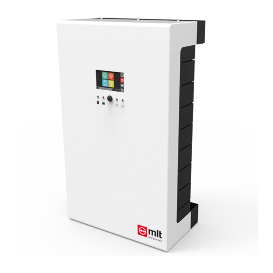
An overview of the Inverter’s Human Machine Interface System The Powerstar 10H includes a touch screen display, three status LEDs, an on/off switch, a start/stop button, and an ethernet port for web-based monitoring/control. Together these make up the Human Machine Interface system. 5.1 The Touch Screen Display As shown in Figure 5, the Powerstar 10H has a touch screen display on its front. -
Page 12: The Control Screen
between showing power flow (i.e. kW or kVA) and/or voltage (V) or current (Amps) click on the purple units icon. The description of each of the icons is given in Table 1. Table 1. A table describing the icons shown on the dashboard screen of the touch screen display. -
Page 13: The History Screen
5.1.3 The History Screen Clicking on the third icon from the top in the navigation pane will take the user to the History (Charts and Events) screens. On this screen, the user can cycle between sub-screens. Namely: a plot of the power measured at the inverter’s source port over the last 24 hours, ... -
Page 14: Buttons And Switches
5.2 Buttons and Switches The Powerstar has an on/off switch and a start/stop push button on the underside of the enclosure as shown in Figure 4. 5.2.1 The On/Off Switch When this switch is in the off position the inverter will stay in System Off mode and will not respond to start/stop instructions. -
Page 15: The Ac Source Led
The following tables describe what the status LEDs indicate based on their colour and whether they are blinking or not. 5.3.1 The AC Source LED LED status Notes No (or very low) voltage is detected on the inverter’s source port. Green - Blinking The source is within acceptable bounds but the inverter’s internal source relays are still open, i.e. -
Page 16: The Battery Led
5.3.3 The Battery LED LED status Notes Blinking / Flashing The inverter is being charged (i.e. current is flowing into the battery). Green The battery State of Charge (SoC) is 64% or more. Or on a Lead Acid battery, the battery voltage is above 48 V. Orange The battery SoC is between 37% and 64%. - Page 17 PAGE PS10-APP01 – V0.02 – 2019/09/11...
Need help?
Do you have a question about the POWERSTAR 10 and is the answer not in the manual?
Questions and answers