
Related Manuals for TSI Instruments DUSTTRAK 8535

Summary of Contents for TSI Instruments DUSTTRAK 8535
- Page 1 DUSTTRAK AEROSOL MONITOR ™ ENVIRONMENTAL ENCLOSURE MODEL 8535 (FOR DUSTTRAK™ II AND DRX AEROSOL MONITOR MODELS 8530 AND 8533) OPERATION AND MAINTENANCE MANUAL P/N 6002097, REVISION N OCTOBER 2020...
- Page 3 Copyright© TSI Incorporated / 2008-2020 / All rights reserved. Part Number 6002097 / Revision N / October 2020 Address TSI Incorporated / 500 Cardigan Road / Shoreview, MN 55126 / USA Fax No. (651) 490-3824 LIMITATION OF WARRANTY AND LIABILITY (effective April 2014) (For country-specific terms and conditions outside of the USA, please visit www.tsi.com.) Seller warrants the goods, excluding software sold hereunder, under normal use and service as described in the operator's manual, shall be free from defects in workmanship...
- Page 4 TO THE EXTENT PERMITTED BY LAW, THE EXCLUSIVE REMEDY OF THE USER OR BUYER, AND THE LIMIT OF SELLER'S LIABILITY FOR ANY AND ALL LOSSES, INJURIES, OR DAMAGES CONCERNING THE GOODS (INCLUDING CLAIMS BASED ON CONTRACT, NEGLIGENCE, TORT, STRICT LIABILITY OR OTHERWISE) SHALL BE THE RETURN OF GOODS TO SELLER AND THE REFUND OF THE PURCHASE PRICE, OR, AT THE OPTION OF SELLER, THE REPAIR OR REPLACEMENT OF THE GOODS.
-
Page 5: Table Of Contents
Contents Contents ..................... iii Safety Information ................v Laser Safety .................... vi Labels ..................... vii Description of Caution/Warning Symbols ..........viii Caution and Warning Symbols .............. viii Reusing and Recycling ................viii Chapter 1 Parts Identification and Unpacking ....... 1 Parts Identification: Environmental Enclosure ......... - Page 6 Chapter 4 Maintenance ..............47 Daily Maintenance Checks ..............47 Cleaning the Aerosol Inlet ..............47 Cleaning the Respirable Aerosol Inlet ............ 47 When to Change the Battery ..............47 Replacing the Battery Pack ..............48 Recharging the Battery Packs ..............48 Battery Pack Life ..................
-
Page 7: Safety Information
Safety Information W A R N I N G The DustTrak™ II/DRX aerosol monitor is not rated for intrinsic safety. The DustTrak™ monitor, with the Environmental Enclosure, must NEVER be operated under conditions where there is a risk of fire or explosion. -
Page 8: Laser Safety
NO T E Prior to using the Battery Pack for the first time, a full recharge is recommended. Recharging Battery Pack(s) immediately after use (within one hour maximum) is critical to obtaining optimal recharge time, battery health, and battery life. Laser Safety •... -
Page 9: Labels
When operated according to the manufacturer’s instruction, this device is a Class I laser product as defined by U.S. Department of Health and Human Services standards under the Radiation Control for Health and Safety Act of 1968. A certification and identification label like the one shown below is affixed to each instrument. -
Page 10: Description Of Caution/Warning Symbols
Description of Caution/Warning Symbols Appropriate caution/warning statements are used throughout the manual and on the instrument that require you to take cautionary measures when working with the instrument. Caution C A U T I O N Failure to follow the procedures prescribed in this manual might result in irreparable equipment damage. -
Page 11: Chapter 1 Parts Identification And Unpacking
Chapter 1 Parts Identification and Unpacking Carefully unpack the Model 8535 DustTrak™ Aerosol Monitor Environmental Enclosure from the shipping container. Use the tables and illustrations below to make certain that there are no missing ® ® components. Contact TSI Incorporated (TSI ) immediately if anything is missing or damaged. - Page 12 Inlet Assembly (sampling) Inlet Ring Heat Shield Mount Location DC Power Connector AC Adapter Mount Location Antenna Cable Strain Relief and Plug Antenna Mount Location USB Pass Through Connection Figure 2: Outside Views of Environmental Enclosure Chapter 1...
-
Page 13: Unpacking The Model 8535 Dusttrak™ Aerosol Monitor Environmental Enclosure
Unpacking the Model 8535 DustTrak™ Aerosol Monitor Environmental Enclosure Compare all the components you received with those listed in the ® table below. If any parts are missing, contact TSI Incorporated. Item Part Number Description 801567 Environmental Enclosure Omni- Direct Inlet with Extended Rain Cap Refer to Sample Inlet Tubing... -
Page 14: Model 8535 Dusttrak™ Aerosol Monitor Environmental Enclosure Optional Accessories
Item Part Number Description Refer to Transport Inlet Plug 801830 accessory kit. Refer to Tripod Mount 801830 Screw Plug accessory kit. Refer to Tripod Mount 801830 Screw Plug Wrench accessory kit. Refer to Antenna Cable 801830 Fitting Plug accessory kit. 6002097 Model 8535 DustTrak™... - Page 15 Item Part Number Description 801817 Dual Battery Wiring Harness (For use with 2 battery packs, See Chapter 3 details) 801808 Replacement 12 VDC Battery Pack 801809 Replacement 12 VDC Battery Pack Charger 801810 Heat Shield Assembly 854057 Tripod Parts Identification and Unpacking...
- Page 16 Item Part Number Description 801811 Solar Cell Power System 801901 GSM/GPS Communication Modem with 8535 mounting kit. 801850 Heated Inlet Accessory 801850 with Auto Zero Module 801851 Heated Inlet Accessory 801851 without Auto Zero (for users who currently own an Auto Zero Module) 801830 Environmental...
- Page 17 Item Part Number Description 801906 Router Mounting Kit Parts Identification and Unpacking...
- Page 18 (This page intentionally left blank) Chapter 1...
-
Page 19: Chapter 2 Setting Up
Chapter 2 Setting Up The setup of the Environmental Enclosure is an important part in allowing reliable and accurate sampling of aerosols in a wide range of ® conditions. TSI cannot ensure accurate measurements if any of the components are set up incorrectly. Failure to follow these procedures could result in damage to the enclosure or its components. -
Page 20: Install Heat Shield Assembly (Optional Accessory)
NO T ES Make sure that a thin film of vacuum grease is coating both O-rings on the inlet tube to ensure a good seal before installing it. DO NOT use the Respirable Aerosol Inlet in the rain. As it will aspirate rainwater into the cyclone body. - Page 21 3. Attach the Heat Shield Assembly to the top of the Enclosure, ensuring that the sealing washers are in place, and tighten the lock washers to secure it in place (Figure 5). Figure 5: Attach Heat Shield to the top of the Enclosure 4.
-
Page 22: Install Water Trap Bottle
Install Water Trap Bottle The translucent bottle that attaches to the bottom of the inner inlet is used to collect any water that is drawn into the sampled flow. This prevents water from reaching the DustTrak™ II/DRX aerosol monitor and damaging it. The bottle is installed on the Environmental Enclosure when it is shipped. -
Page 23: Install Sample Inlet Tubing
Install Sample Inlet Tubing The Sample Inlet Tubing directs the sample aerosol flow from the Sample Inlet to the DustTrak™ monitor. 1. Make sure that the Inlet Fitting is inserted into the Inner Inlet Ring as shown in Figure 8. 2. -
Page 24: Install Impactor In The Sample Flow (Optional Accessory)
Install Impactor in the Sample Flow (optional accessory) Optional Impactors are available as accessories to the DustTrak™ II/DRX aerosol monitor. These Impactors can be placed in the Sample Flow in the Environmental Enclosure system as detailed below. NO T E Refer to the DustTrak™... -
Page 25: Install Battery Pack System (Optional Accessory)
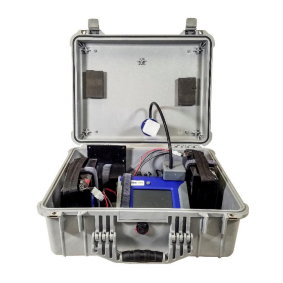
Install Battery Pack System (optional accessory) An optional 12 VDC Battery Pack provides power to the DustTrak™ monitor and optional accessories. W A R N I N G ® Use only TSI supplied Battery Packs, P/N 801808. ® 1. VELCRO straps are provided to secure the Battery Pack System ®... - Page 26 2. Lift the Battery Pack using the lifting strap and place in the Enclosure bracket as shown in Figure 11, keeping the battery output connector facing away from you. Figure 11: Install the Battery Pack System 3. Tightly secure the Battery Pack System in place using the ®...
-
Page 27: Install External Weatherproof Ac Adapter (If Desired)
Figure 12: Install the Dual Battery Pack System Install External Weatherproof AC Adapter (if desired) Use the external weatherproof AC/DC adapter when dedicated AC power is available for powering the instrument. 1. Remove the external AC adapter mounting screws from the right side of the Enclosure as shown in Figure 13. - Page 28 2. Attach the AC adapter to the Enclosure as shown in Figure 14, using the existing mounting screws and sealing washers. Figure 14: Attach the Adapter to the Enclosure 3. Connect the DC power output cable from the adapter to the Enclosure DC input connector as shown in Figure 15.
-
Page 29: Install Dusttrak™ Monitor In The Environmental Enclosure
Install DustTrak™ Monitor in the Environmental Enclosure The internal bracket of the Environmental Enclosure is designed to hold the DustTrak™ monitor securely in place, using the provided ® VELCRO straps. ® 1. VELCRO straps are provided to secure the DustTrak™ monitor ®... -
Page 30: Connecting Internal Usb Cables
Connecting Internal USB Cables Connect the DustTrak™ monitor to the external USB pass- through connector. 1. If using Model 8530 EP or 8533 EP with external pump, make sure you install the exhaust adapter on the exhaust of the DustTrak™ monitor as shown below. Figure 18: Install Exhaust Adapter 2. - Page 31 Figure 20: Connect Monitor Power Cable to Pump 3. Likewise, connect the External Pump Flow Tube (P/N 801798) between the DustTrak™ monitor and the External Pump Module (P/N 801675) as shown below in Figure 21. Figure 21: Connect External Pump Flow Tube 4.
-
Page 32: Connecting Sample Tubing
Figure 22: Connect USB Cable for Pass-through Connecting Sample Tubing A length of tubing is provided to transport the aerosol from the external inlet to the DustTrak™ II/DRX aerosol monitor inlet. Before attempting to sample, make sure that this tubing is securely fastened to the barbs from both of the inlets. -
Page 33: Supplying Power To The Dusttrak™ Ii/Drx Aerosol Monitor (And Optional Accessories)
Supplying Power to the DustTrak™ II/DRX Aerosol Monitor (and optional accessories) The DustTrak™ II/DRX Aerosol Monitor may be powered in one of three ways when used with the Model 8535 Environmental Enclosure: 1. Use external weatherproof AC adapter, when AC power is desired. - Page 34 Using the Internal Battery Pack (optional accessory) The battery packs supplied with the Environmental Enclosure allow for extended use of the DustTrak™ monitor The battery pack enables the DustTrak™ monitor to operate for at least 34 hours (even in cold conditions).
-
Page 35: Mounting The Environmental Enclosure To A Surveyor Tripod
NO T E Prior to using the Solar Cell Power System for the first time, a full recharge of the Solar Battery is recommended. Mounting the Environmental Enclosure to a Surveyor Tripod The Environmental Enclosure may be mounted to a standard surveyor tripod equipped with a 5/8”-11 threaded stud. -
Page 36: Transporting The Environmental Enclosure
C A U T I O N DO NOT place the Environmental Enclosure in direct contact with the ground. The bottom of the Environmental Enclosure contains an exhaust port that may allow water to enter the enclosure, resulting in damage to the DustTrak™ II and DRX aerosol monitors. -
Page 37: Setting-Up The Solar Cell Power System (Optional Accessory)
Setting-up the Solar Cell Power System (optional accessory) The full Solar Cell Power System is shown in Figure 26. The following section details the setup of this system. I M P O R T A N T Make all Solar Cell Power System electrical connections in the order outlined below. - Page 38 Figure 27: Install the Solar Battery and Connect to Controller 2. The next step is to attach the provided power cables with waterproof connectors to each Solar Cell. Remove the Solar Cell from its packaging and access the junction box on the end of the panel. Remove the screws and sealing strip from inside the box and set aside.
- Page 39 3. Next, attach the power cable to the Solar Cell screw terminals as shown in Figure 29 or Figure 30. NO T E Make sure the wires are connected as shown below. Connecting the wires incorrectly can cause severe damage to the Solar Power System.
- Page 40 Figure 30: Attach Power Cable to Screw Terminals Chapter 2...
- Page 41 4. With the wires tightened, secure the terminal block in its retaining clips, and tighten the strain relief connections to the power cable as shown in Figure 31. Figure 31: Secure Terminal Block and Tighten Strain Relief Setting Up...
- Page 42 5. Next, attach the sealing strip to the inside of the junction box cover, as shown in Figure 32. Figure 32: Apply Sealing Strip to Junction Box Cover 6. Then attach the cover to the junction box using the supplied screws, as shown in Figure 33.
- Page 43 7. Now attach the two structural angle pieces to the solar panels using the supplied hardware. Fasten each angle piece in four locations as indicated by the red circles (see Figure 46). Figure 34: Assemble the Solar Cells on the Mounting Frame Setting Up...
- Page 44 8. Attach the two shorter structural angles to the angle pieces installed in the previous step (see Figure 35). Figure 35: Attach Shorter Structural Angles Chapter 2...
- Page 45 9. Complete the frame, by fastening the two flat bar pieces and mounting feet to the structural angles (see Figure 36 and Figure 37. NO T E Additional fastening locations are present in the flat bar and angle pieces, which can be used to adjust the solar panel angle.
- Page 46 Figure 37: Fasten Mounting Feet NO T E For best results, mount the solar panels at an angle directly pointed at the path of the sun, allowing for maximum energy to be collected by the solar panels. Reference the solar panel manufacturer’s instructions for angle recommendations.
- Page 47 NO T E DO NOT connect the Solar Cells directly to the 8535 Environmental Enclosure as this may result in damage to the DustTrak™ Aerosol Monitor. The Solar Cells MUST be connected to the Solar Battery Enclosure Box so they can be regulated by the Solar Charge Controller.
-
Page 48: Setting-Up Trakpro™ Data Analysis Software
NO T E The Solar Charge Controller has built-in low voltage cutout protection for the Solar Battery. If extended non-sunlight conditions occur, causing the Solar Battery to become deeply discharged, the Solar Charge Controller temporarily cuts off output power. The Red LED on the Solar Charge Controller will illuminate when this condition occurs. -
Page 49: Chapter 3 Operation
Chapter 3 Operation Overview The DustTrak™ Environmental Enclosure can be used in conjunction with the DustTrak™ II and DustTrak™ DRX aerosol monitor for many different applications. Its primary use is in outdoor applications to give the DustTrak™ monitor protection from the elements and the ability to sample efficiently in different wind speeds. -
Page 50: Changing And Re-Charging The Battery Packs
Changing and Re-charging the Battery Packs If using a DustTrak™ monitor, change the battery packs within the Environmental Enclosure at least every 34 hours of use. However, if using a DustTrak™ monitor with External Pump, change the battery packs within the Environmental Enclosure every 23 hours of use. ®... - Page 51 External Pump, the battery pack should be removed from service and properly recycled in accordance with local environmental regulations. NO T E Prior to using the Battery Pack for the first time, a full recharge is recommended. Recharging Battery Pack(s) immediately after use (within one hour maximum) is critical to obtaining optimal recharge time, battery health, and battery life.
- Page 52 2. Select the manual switch setting on the back of the charger to the setting that matches the correct power distribution present in your local area (i.e., 115 VAC or 240 VAC). 3. Connect the charger to the battery pack by connecting the battery pack output connector to the mating charger connector.
- Page 53 7. The charger is equipped with a time-out feature. The time-out feature is designed to prevent over-charging aging battery packs or battery packs having poor health due to abuse. The time-out feature may also protect against charger faults. The time-out feature does NOT trigger during normal operation of charging healthy battery packs.
-
Page 54: Zeroing The Dusttrak™ Ii/Drx Aerosol Monitor
The Dual Battery Wiring Harness is water-resistant, but NOT water- proof, the cable may fail if subjected to abundant water exposure including submersion in water. Zeroing the DustTrak™ II/DRX Aerosol Monitor Always zero the DustTrak™ II and DustTrak™ DRX monitor before beginning a sample. -
Page 55: Checklist For Sampling With The Environmental Enclosure
Checklist for Sampling with the Environmental Enclosure Before beginning a sample, check to see that all of the following conditions are satisfied: ✓ All components are properly installed into the enclosure as described in the Setup section. ✓ The DustTrak™ II/DRX monitor has been zeroed at the temperature at which it will be sampling (if possible). - Page 56 To download a file under normal data-logging operations, do the following: 1. Open the Environmental Enclosure. 2. Discontinue sampling. 3. Attach the USB cable from the DustTrak™ monitor to a notebook computer. 4. Download the data file using TrakPro™ software. Chapter 3...
-
Page 57: Chapter 4 Maintenance
Chapter 4 Maintenance Daily Maintenance Checks Check the DustTrak™ II/DRX aerosol monitor a minimum of once a day to change the battery pack(s) and make sure that the instrument is operating properly. A visual inspection of the instrument and case can ensure that the water trap is empty, the sampling inlet is unobstructed and the tubing is not kinked. -
Page 58: Replacing The Battery Pack
If a battery pack has been forgotten and is left connected to a running DustTrak™ monitor the extended-life battery will automatically quit delivering power to the DustTrak™ monitor after its voltage drops below 10.5 V. This cutoff provides protection to the battery pack, which will extend the lifetime of the pack. - Page 59 The information below is NOT intended as a substitute to the charger manual. The charger manual will cover all important warnings and operating instructions for using the charger. The steps below guide you through the battery pack charging process steps. 2.
-
Page 60: Battery Pack Life
prevent the possibility of arcing during the battery disconnect process. 7. The charger is equipped with a time-out feature. The time-out feature is designed to prevent over-charging aging battery packs or battery packs having poor health due to abuse. The time-out feature may also protect against charger faults. - Page 61 It is important to remove a battery pack from service if signs of diminished run-time or longer charge time are observed. These are signs of battery pack aging and poor general battery health. A battery pack in good health will take near 8 to 9 hours to fully charge. A battery pack that provides 30% less product run-time than expected is ready to be removed from service.
-
Page 62: Emptying The Water Trap
8. Using a DC Volt Meter, connect the “red” (positive) test lead of the meter to the battery pack output connector at the conductor located closest to the triangle-shaped side of the connector. Please see the illustration. 9. Connect the “black” (negative) test lead of the DC Volt Meter to the battery pack output connector at the bottom... -
Page 63: Chapter 5 Troubleshooting The Environmental Enclosure
Chapter 5 Troubleshooting the Environmental Enclosure The table below lists the symptoms, possible causes and recommended solutions for common problems encountered with the DustTrak™ II/DRX Aerosol Monitor Environmental Enclosure. Symptom Possible Cause Corrective Action DustTrak™ Uncharged Battery Make sure Battery Pack is monitor Pack. - Page 64 Symptom Possible Cause Corrective Action Readings Leak in the inlet. Make sure the upper inlet assembly and the water trap unusually are screwed in tightly. low. (cont.) Make sure tubing is secured on the enclosure barb and the DustTrak™ monitor. Make sure inlet assembly O-ring is in place.
-
Page 65: Appendix A Specifications
Appendix A Specifications Specifications are subject to change without notice. Environment Enclosure Sampling Conditions Sensor Type 0 to 22 mph (0 to 36 kph) Operating 32 to 120F (0 to 50C) Temperature Storage -4 to 140F (–20 to 60C) Temperature Physical External dimensions 8.1 x 16.9 x 20.6 in. -
Page 66: Solar Power System
Internal Battery System Internal Battery Pack 12 VDC, 22 Ah Battery Run-time DustTrak™ II/DRX with internal pump: 34 to 36 hours (typical) DustTrak™ II/DRX with external pump: 21 to 24 hours (typical) DustTrak™ II/DRX with external pump and Heated Inlet accessory: 15 hours (typical) Battery Charge Time 8 to 9 hours at 72F (22C) (New battery, deep discharge to 95% charge) - Page 67 Physical (Solar Panels) Dimensions (HWD) 2 x 21 x 48 in. (5 x 53 x 122 cm) each Weight 17 lbs. (7.7 kg) each Physical (Battery and Case) Dimensions (HWD) 8.5 x 15.3 x 17 in. (22 x 39 x 43 cm) Weight 85 lb.
- Page 68 (This page intentionally left blank) Appendix A...
- Page 70 TSI Incorporated – Visit our website www.tsi.com for more information. Tel: +1 800 680 1220 India Tel: +91 80 67877200 Tel: +44 149 4 459200 China Tel: +86 10 8219 7688 France Tel: +33 1 41 19 21 99 Singapore Tel: +65 6595 6388 Germany Tel: +49 241 523030 P/N 6002097 Rev.
Need help?
Do you have a question about the DUSTTRAK 8535 and is the answer not in the manual?
Questions and answers