Table of Contents
Advertisement
Quick Links
Advertisement
Table of Contents

Subscribe to Our Youtube Channel
Summary of Contents for Nilar Ferroamp Home Box
- Page 1 21‐0001 & 21‐0002 ...
- Page 2 Thank you for purchasing a Nilar product! It is required to read and understand these instructions carefully for a safer installation and operation, as well as optimum performance and a longer service life. Keep this manual in a safe place for future reference. This manual may be modified and updated without prior notice. Contact Nilar for validation. Colors used in illustrations of e.g. cables are only illustrative and might deviate from the actual color. Without written permission from Nilar this manual is not to be copied or transferred for other purposes, neither in its entirety nor parts of it. The product described in this manual is manufactured in compliance with the Low Voltage Directive (LVD) 2014/35/EU, the Electromagnetic Compatibility (EMC) Directive 2014/30/EU and the restrictions of certain hazardous substances according to RoHS Directive 2011/65/EU. The product contains nickel metal hydride battery packs that follow the EU‐directive 2006/66/EG (‘Battery Directive’). The battery packs do not contain the heavy metals lead, mercury or cadmium. The product adheres to the Waste Electrical and Electronic Equipment (WEEE) Directive 2012/19/EU. This means that the manufacturer/importer has a responsibility that the manufactured products are collected, taken care of and recycled after they have reached the end of their lifespan. Nilar products are in compliance with Regulation (EC) No. 1907/2006 concerning the Registration, Evaluation, Authorization and the restriction of Chemicals (REACH). We check that our suppliers comply with REACH requirements for all the materials and components they deliver to us. ©Nilar AB. All rights reserved. Document identification: 73‐H006 Version Status Date 4.0 Previous release 2019‐10‐07 4.3 Internal revision 2020‐04‐14 5.0 Released revision 2020‐04‐23 ...
- Page 3 2. Technical support and warranty References 2 3. Environment Content, recycling 3 4. Function description General description of product 4 5. Transportation, lifting and Instructions, conditions 10 storage 6. Installation Instructions for installation 14 7. Operation Checklist 31 8. Maintenance Recommendations, schedules 32 9. Decommissioning Instructions, references 33 10. Troubleshooting Instructions 34 Document ID: 73‐H006. Copyright © Nilar AB. All rights reserved. ...
- Page 4 Energy Management System ESO Energy Storage Optimizer IMU Integrated Monitoring Unit LED Light Emitting Diode LVD Low Voltage Directive MCB Miniature Circuit Breaker MSDS Material Safety Data Sheet NiMH Nickel Metal Hydride PLC Programmable Logic Controller PPE Personal Protective Equipment PSN Proper Shipping Name RCD Residual‐Current Device REACH Registration, Evaluation, Authorization and the restriction of Chemicals RoHS Restrictions of Hazardous Substances SoC State of Charge VDC Volt of Direct Current WEEE Waste Electrical and Electronic Equipment Document ID: 73‐H006. Copyright © Nilar AB. All rights reserved. ...
-
Page 5: Table Of Contents
General schematic overview .......................... 5 System specification ............................ 5 Measurements.............................. 6 Battery string .............................. 6 Battery pack specification and build‐up ...................... 6 Integrated Monitoring Unit (IMU) ........................ 7 Connections IMU ............................. 8 5. Transportation, lifting and storage .................... 10 Transportation ............................... 11 Moving and lifting ............................ 12 Storage ................................ 13 6. Installation ............................ 14 General conditions on site .......................... 15 Scope of supply .............................. 15 Placement .............................. 16 Adjustment .............................. 16 Attachment .............................. 17 Dismantling of cabinet prior to installation .................... 17 Document ID: 73‐H006. Copyright © Nilar AB. All rights reserved. ... - Page 6 6.10 Placement of battery packs ........................... 22 6.11 Connection of battery packs .......................... 24 6.12 Assembly of cabinet ............................ 30 7. Operation ............................ 31 Checklist for operation .......................... 31 8. Maintenance ............................. 32 Protective measures during maintenance ..................... 32 Inspection and monitoring .......................... 32 9. Decommissioning .......................... 33 9.1 Temporarily decommissioning ........................ 33 9.2 Permanent decommissioning ........................ 33 10. Troubleshooting.......................... 34 Document ID: 73‐H006. Copyright © Nilar AB. All rights reserved. ...
- Page 7 Figures Figure 1: Indication of Serial number sticker on the Nilar Home Box .................. 2 Figure 2: Nilar Hydride® battery pack 144VDC (12 modules) .................... 4 Figure 3: Nilar EC Home Box 6kWh – Ferroamp ......................... 4 Figure 4: General schematic overview ............................ 5 Figure 5: Home Box unit measurements (excl. mounting brackets) .................. 6 Figure 6: Measurement illustration of 144V battery pack with length incl. IMU (excl. insulation tray) ........ 6 Figure 7: 144VDC battery pack with IMU on front ........................ 7 Figure 8: Disconnection of cable connectors .......................... 7 Figure 9: Overview of IMU with cover lid removed ........................ 8 Figure 10: Indicated connection points of IMU ‘1’ indicates pin 1 of connection .............. 9 Figure 11: Orientation of battery pack ............................. 10 Figure 12: Battery pack incl. lifting straps .......................... 12 Figure 13: Cabinet with indicated lifting points ........................ 12 Figure 14: Scope of supply ................................ 15 Figure 15: Nilar Home Box with indicated minimum distances to neighboring objects ............ 16 Figure 16: Indication of support legs ............................ 16 Figure 17: Mounting brackets for wall attachment........................ 17 Figure 18: Removal of cover lid .............................. 17 Figure 19: Dismantling of corner tops ............................ 18 Figure 20: Before and after removal of side plate with indicated suspension ................ 18 Figure 21: Before and after removal of front plate with indicated suspension ............... 18 Figure 22: Before and after removal of top plate ........................ 19 Figure 23: Before and after removal of BMS cover ........................ 19 Figure 24: Location of cable entry for Ferroamp EnergyHub system power cable on the backside of the cabinet .... 19...
- Page 8 Figure 35: Before and after IMU cover lid removal ........................ 24 Figure 36: Installation of current sensor cable on IMU of battery pack ‘D’ ................ 24 Figure 37: Installation of ingoing CANopen communication cable into CAN2 socket on IMU .......... 24 Figure 38: Installation of fan connection on IMU ........................ 25 Figure 39: Installation of 24VDC power supply connection on IMU .................. 25 Figure 40: Installation of ambient temperature sensor connection on IMU of battery pack ‘A’ .......... 25 Figure 41: Detail view of cable entry on cover lid of IMU ...................... 26 Figure 42: Installed negative (‐) cable (IMU connections are not displayed) ................ 26 Figure 43: Installed interpack cable between battery pack ‘A’ and ‘B’ (IMU connections are not displayed) ...... 27 Figure 44: Installed interpack cable on positive (+) terminal for battery pack ‘B’ (IMU connections are not displayed) .. 27 Figure 45: Installed interpack cable on negative (‐) terminal for battery pack ‘C’ (IMU connections are not displayed) .. 28 Figure 46: Installed interpack cable between battery pack ‘C’ and ‘D’ (IMU connections are not displayed) ....... 28 Figure 47: Current sensor displayed with correct installation direction .................. 29 Figure 48: Installed positive (+) cable including current sensor (remaining IMU connections are not displayed) .... 29 Figure 49: Location of fuses within the BMS .......................... 30 Figure 50: WEEE symbol for separate disposal ........................ 33 Document ID: 73‐H006. Copyright © Nilar AB. All rights reserved. ...
- Page 9 Tables Table 1: Specification for Nilar Home Box .......................... 5 Table 2: Description of visual signals ............................ 8 Table 3: Relation between temperature and the recommended maximum storage time at 75% SoC initial capacity .. 13 Table 4: Denomination table .............................. 15 Document ID: 73‐H006. Copyright © Nilar AB. All rights reserved. ...
-
Page 10: Safety Information
1. SAFETY INFORMATION 1. Safety Information Rupture disc may release electrolyte during abnormal use. We therefore recommend wearing safety glasses. This chapter contains general safety information that is Risk for electrical hazards if product is WARNING! applicable to the Nilar Home Box. exposed to rain or moisture. To avoid personal injury, do not perform any servicing Do not operate the product with suspected WARNING! unless you are qualified to do so. Refer to all safety failures. If you suspect that the product is damaged, summaries prior to performing installation, operation, have it inspected by qualified service personnel. maintenance and decommissioning. For more detailed Do not block or cover the rupture disc outlet information, contact Nilar and request the Material WARNING! on the battery pack. Safety Data Sheet (MSDS). If a fire occurs, it can be extinguished by using WARNING! . Ensure that fire extinguishers are available. 1.1 Safety markings in this instruction If the battery pack(s) is damaged CAUTION! mechanically, the following may occur: WARNING! High heat generation on the surface of the battery cells. The exclamation mark within an ... -
Page 11: Technical Support And Warranty
2. TECHNICAL SUPPORT AND WARRANTY Regarding the warranty conditions, please contact your 2. Technical support and warranty authorized local Nilar representative. CAUTION! Please make sure to always have the serial number of your product(s) available for warranty and technical support matters. Regarding technical support, please contact your authorized local Nilar representative and have the serial number available. The serial number can be found in four (4) different locations of the Nilar Home Box, on one of the side plates ①, as a lose sticker in the plastic pocket for the quick‐guide ②, on the top plate below the cover lid ③ and on the backplate ④. ① ② ③ ④ Figure 1: Indication of Serial number sticker on the Nilar Home Box 2 (34) Document ID: 73‐H006. Copyright © Nilar AB. All rights reserved. ... -
Page 12: Environment
3. ENVIRONMENT 3. Environment 3.4 Battery pack When the Nilar battery pack has reached its end of life, This chapter will inform about the composition of Nilar Nilar takes the full responsibility for the recycling products and hence give the user valuable information process by accepting the complete battery packs back. on partly how to treat the product and partly how it is The recycling process used ensures that most of the recycled the day it has reached the end of its lifecycle. materials are reused or recycled appropriately. The Please contact Nilar in order to find your closest main components in the battery packs consist of: representative. Plastic, aluminum, Ni‐plated steel, carbon steel and active materials. Contact your authorized local Nilar representative for a more detailed composition 3.1 Compliance specification. Nilar products are compliant with the following directives and regulations: 3.5 Integrated Monitoring Unit (IMU) EU‐directive 2006/66/EC (‘Battery Directive’). The IMU can be divided into two categories of The battery packs do not contain the heavy materials. First there is the outer shell which is made of metals lead, mercury or cadmium. plastic and must be recycled as such. Secondly it ... -
Page 13: Function Description
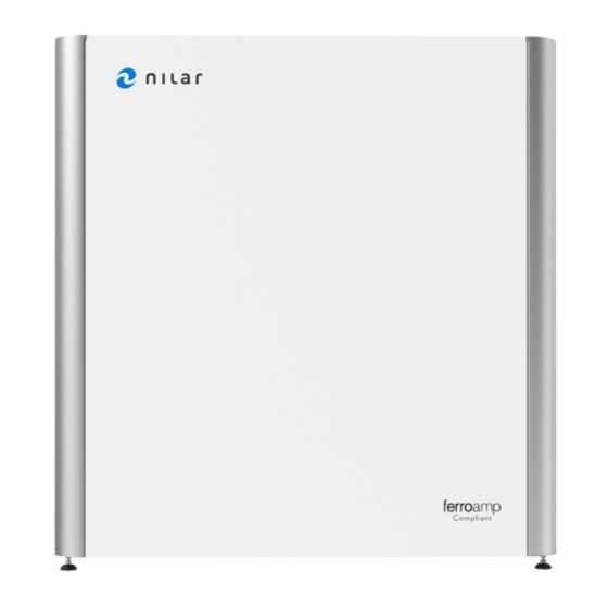
4. FUNCTION DESCRIPTION 4. Function description Nilar Home Box is a solution for grid connected energy storage. It can accept electrical energy from the grid, store the energy and provide energy when required. Between Nilar Home Box and the grid it is required to connect the Ferroamp EnergyHub which converts AC to DC and vice versa. The operation is fully automated and monitored externally via the Ferroamp EnergyHub Cloud tool. Nilar Home Box contains innovative and environmentally friendly Nilar Hydride® batteries (NiMH) that are based on a bipolar modular battery Figure 2: Nilar Hydride® battery pack 144VDC (12 modules) solution. The modules, in turn, can be assembled into battery packs of different voltages (VDC) in a simple stacking operation. These battery packs are arranged in a battery string consisting of four (4) series connected battery packs. To optimize performance, Nilar Home Box is equipped with a BMS. The BMS monitors the status of the battery packs and can manage the operation in order to optimize performance. The BMS communicates with the Ferroamp EnergyHub via a CANopen communication protocol. Amongst others information about maximum allowed charge and discharge power, State of Charge (SoC), warnings and alarms are exchanged. Figure 3: Nilar EC Home Box 6kWh – Ferroamp ... -
Page 14: General Schematic Overview
4. FUNCTION DESCRIPTION 4.1 General schematic overview 4.2 System specification The energy flow in and out of Nilar Home Box is Table 1: Specification for Nilar Home Box controlled by the Ferroamp EnergyHub which in turn is setting the Electric Storage Optimizer (ESO) power. Data Unit The Nilar BMS monitors the battery energy flow and Rated energy kWh provides this data to the Ferroamp EnergyHub. Nominal voltage, battery string 576 VDC Battery string voltage range 480‐768 VDC Nominal voltage, ESO 760 VDC Max. continuous charging kW power Max. continuous discharging 6 kW power 945x Figure 4: General schematic overview ... -
Page 15: Measurements
4. FUNCTION DESCRIPTION 4.3 Measurements 4.4 Battery string The outer measurements of Nilar Home Box are as Each Nilar Home Box contains a set of four (4) battery follows: packs. This set of battery packs is referred to as a battery string. The battery packs are connected in series to match the required system voltage. The following components are found in a Nilar Home Box battery string. Battery packs with IMU’s 4 pcs Current sensor 1 pcs Fan units 4 pcs CANopen cables 5 pcs 24VDC power cable 4 pcs String power cables 5 pcs Ambient temperature sensor 1 pcs 4.5 Battery pack specification and build‐up ... -
Page 16: Integrated Monitoring Unit (Imu)
Cover lid for connections of IMU Integrated Monitoring Unit (IMU) Figure 7: 144VDC battery pack with IMU on front Data monitored by the IMU: Module voltages (up to 12 modules per battery pack). Battery pack voltage. Battery pack temperature (1 sensor per battery pack). Battery pack pressure (1 sensor per battery pack). Ambient temperature sensor (1 sensor per cabinet). String current (1 sensor per battery string). For a more detailed description of the IMU, please refer to the CAN interface description (doc. Id: SPN‐170063‐88‐H001). 7 (34) Document ID: 73‐H006. Copyright © Nilar AB. All rights reserved. ... -
Page 17: Connections Imu
Green Blue Green Blue etc. ② An IMU with an active alarm will replace the green Figure 9: Overview of IMU with cover lid removed signal and hence flash: Red off Red off etc. An IMU in the start‐up sequence with an active alarm will flash: Red Yellow Red Yellow etc. An IMU in power save mode with an active alarm will flash: Red Blue Red Blue etc. 4.7.2 Reset button (②) By pushing the Reset button, the IMU will be manually restarted. 8 (34) Document ID: 73‐H006. Copyright © Nilar AB. All rights reserved. ... -
Page 18: Figure 10: Indicated Connection Points Of Imu '1' Indicates Pin 1 Of Connection
4. FUNCTION DESCRIPTION 4.7.3 Overview ‐ connections ● 4.7.6 Address setting (⑤, brown ) The following connections/switches are available on the When connecting several battery packs to form a IMU and their function is explained in the subsequent battery string, every battery pack/IMU requires a sections. unique identification (address). This identification is set by the DIP‐switch. Note! The indication numbers in the following figure correlate to various headings of chapter 4.7. Note! The switch setting is already made by Nilar prior to delivery. ● 4.7.7 CAN1 and CAN2 (⑥, green The CANopen connections (type: RJ45/8P8C) are used as input and output per battery pack in order to connect 1 the battery string communication. 1 1 ● 4.7.8 Fan (⑦, yellow ) This connection is used to power the cooling fan for 1 each battery pack. ●... -
Page 19: Figure 11: Orientation Of Battery Pack
5. TRANSPORTATION, LIFTING AND STORAGE The battery packs must always be placed in an upright 5. Transportation, lifting and storage position (with the terminals in upper position) during This chapter deals with the conditions that Nilar transportation and storage: products require when being transported, moved, lifted, and stored. WARNING! Always transport and/or store the battery packs on insulating (non‐ conductive) surfaces. CAUTION! Please make sure that the battery packs are positioned in the correct way during transportation and storage. CAUTION! Always wear PPE (Personal Protective Equipment) when handling battery packs. At Figure 11: Orientation of battery pack minimum this includes: Safety glasses, safety shoes with steel toe and electrically insulated gloves. 10 (34) Document ID: 73‐H006. Copyright © Nilar AB. All rights reserved. ... -
Page 20: Transportation, Lifting And Storage
5. TRANSPORTATION, LIFTING AND STORAGE 5.1.2 Transportation of Battery packs 5.1 Transportation Nilar battery packs do not require UN approved When transporting Nilar products, some preparations packaging or marking when transported by sea, road, and precautions must be taken which will be described rail or air. in this part of the chapter. No dangerous goods documentation is required when 5.1.1 Packaging and outside conditions transporting Nilar battery packs by road or rail. A dangerous goods declaration is required if battery CAUTION! packs are transported by sea in quantities of over 100 When performing the visual kg in one transport unit. Nilar battery packs are then inspection, it is important not to defined as dangerous goods, class 9. UN number and remove the battery packs from their Proper Shipping Name (PSN) are UN 3496 and Batteries, original Nilar sealed plastic Nickel Metal Hydride, respectively. packaging. An Air Waybill or similar is required if battery packs are transported by air. Nilar battery packs are not classified CAUTION! as dangerous goods and belong to the entry Batteries, It is important to always pack the dry in the list of dangerous goods in IATA (no UN battery packs in their original Nilar number). If an Air Waybill is used, the words ‘Not sealed plastic packaging with Restricted’ and the Special Provision number (A123) ... -
Page 21: Moving And Lifting
5. TRANSPORTATION, LIFTING AND STORAGE 5.2 Moving and lifting WARNING! The Nilar Home Box must always be emptied of its battery packs and disconnected from any power source before any lift/moving can be performed! CAUTION! Be careful when lifting the battery packs. Nilar recommends using lifting aids and safety shoes with steel toe. Figure 12: Battery pack incl. lifting straps 5.2.2 Nilar Home Box cabinet The cabinet is delivered on a pallet and must always be CAUTION! moved on its pallet by a pallet loader. The cabinet is heavy, be careful In order to lift it of the pallet and for smaller when lifting the cabinet manually adjustment‐movements in connection with e.g. and never lift it alone. Nilar recommends using lifting aids and installation, the cabinet can be lifted manually if lifted safety shoes with steel toe. by its two battery shelfs (as indicated in the following illustration). CAUTION! Always use both straps when lifting and/or carrying the battery pack. ... -
Page 22: Storage
5. TRANSPORTATION, LIFTING AND STORAGE 5.3 Storage CAUTION! Moist conditions can create irreversible damage on Nilar Home Box including but not limited to electrical failure and corrosion. It is important to always keep the battery packs in their original Nilar sealed plastic packaging with moisture absorbent bags during storage. The Nilar Home Box must be stored in dry (< 90% relative humidity and without condensation) and preferably cold conditions. Nilar battery packs can be stored long periods without loss of performance. The following table displays the relation between temperature and the recommended maximum storage time at 75% SoC initial capacity and without intervention. Table 3: Relation between temperature and the recommended maximum storage time at 75% SoC initial capacity Temperature [ C] Time [years] ‐30 to 10 7 11 to 30 5 31 to 40 1,5 41 to 60 28 days Note! The specified years as displayed in the table refer to ... -
Page 23: Installation
6. INSTALLATION 6. Installation CAUTION! This chapter does, amongst others, explain under which Always wear PPE (Personal circumstances a safe installation can take place and Protective Equipment) when provides guidance through the installation of the handling battery packs. At product, step‐by‐step. minimum this includes: WARNING! Safety glasses, safety shoes with steel toe and electrically insulated Do not install Nilar Home Box in gloves. areas that are subject to contamination, such as high levels of airborne dust, metal particles or flammable materials/gases. Do not install where liquids, or any other foreign objects or substances may CAUTION! enter the Nilar Home Box. Do not work alone ‐ in the event of an emergency, another person's WARNING! presence may be essential! The electrical installation must fulfil national/local legislations, regulations, suitable standards and applicable demands from ... -
Page 24: General Conditions On Site
6. INSTALLATION Do not allow direct sunlight on the system. 6.1 General conditions on site The relative humidity should be kept below 90% WARNING! (without condensation). Always install a type B or B+ Residual Current Device (RCD). If an 6.2 Scope of supply RCD of another classification (type The following content is included in one (1) unit of Nilar AC, A or F) is already installed, it Home Box. needs to be replaced with a type B or B+ RCD. For more information regarding the RCD‐installation and RCD‐types, please request the separate Information bulletin from Nilar. CAUTION! Make sure to allow space for emergency evacuation at all times. The minimum distance can vary in different markets and must always ① be in accordance with ② national/local legislation. ③ ④ ... -
Page 25: Placement
6. INSTALLATION 6.3 Placement 6.4 Adjustment Observe the specified minimum distances to WARNING! neighboring objects. Always adjust the support legs so that the cabinet is standing horizontally straight in both directions. In order to balance the Nilar Home Box and compensate for an uneven foundation, it is necessary to adjust the four (4) support legs located in the bottom of the cabinet. By screwing them individually the cabinet can be adjusted to be horizontally straight in both Figure 15: Nilar Home Box with indicated minimum distances to neighboring objects directions. Figure 16: Indication of support legs 16 (34) Document ID: 73‐H006. Copyright © Nilar AB. All rights reserved. ... -
Page 26: Attachment
6. INSTALLATION 6.5 Attachment 6.6 Dismantling of cabinet prior to installation WARNING! In order to be able to attach the cabinet to a wall, install the battery packs and make all the necessary Nilar Home Box must always be connections, the cabinet needs to be disassembled. attached with the mounting brackets to a stable wall. 6.6.1 Dismantling of cover lid Min. distance to wall: 30mm WARNING! Note! Do not attach the cabinet before all the external cables are Beneath the cover lid the Nilar installed. Home Box is equipped with warning The cabinet is equipped with two (2) mounting brackets stickers, please read those carefully that are located on the top portion of the cabinet’s back before proceeding with the installation. plate. The cabinet must be fixed by attaching the mounting brackets with two (2) screws onto a stable wall. The cover lid is fixed by four (4) M6 hex screws. Remove the screws by using a hex driver size 4 and turning it The mounting brackets do not need to be removed counterclockwise in order to loosen the screws. Lift off ... -
Page 27: Figure 19: Dismantling Of Corner Tops
In order to be able to remove the remaining parts it is The two (2) side plates are hinged on six (6) M6 screws. necessary to first remove the four (4) corner tops which Remove the side plates by first sliding them gently hold all the vertical plates in place. upwards to unhook them from their suspensions and thereafter lift them outwards. The corner tops are hold in place by four (4) M6 screws. Note! It might facilitate the later installation of the battery packs if the Remove the screws by using a hex driver size 4 and screws are removed. turning it counterclockwise in order to loosen the screws. Remove the corner tops. Figure 20: Before and after removal of side plate with indicated suspension 6.6.4 Removal of front plate The front plate is hinged on six (6) M6 screws. Remove the front plate by first sliding it gently upwards to unhook it from its suspensions and thereafter lift it outwards. Note! Do not remove or loosen the screws Figure 19: Dismantling of corner tops Figure 21: Before and after removal of front plate with indicated suspension 18 (34) Document ID: 73‐H006. Copyright © Nilar AB. All rights reserved. ... -
Page 28: Connection Of Energyhub System Power Supply
The Ferroamp EnergyHub system upwards a few degrees and thereafter lifting it off. may still provide hazardous voltage and residual energy. Although it is switched off or may appear switched off. WARNING! The negative (‐) wire and the positive (+) wire of the incoming power cables must always be Figure 22: Before and after removal of top plate externally protected by a 10A DC‐ fuse (1000VDC), each. 6.6.6 Dismantling of BMS cover In order to make the necessary connections to the Nilar The externally located Ferroamp EnergyHub system BMS, the BMS cover needs to be removed. power cable is connected to Nilars BMS through the cable entry located on the backside of Nilar Home Box. Remove the BMS cover be removing four (4) M6 screws. Remove the screws by using a hex driver size 4 and turning it counterclockwise in order to loosen the screws. Remove the BMS cover. Note! Do not remove the screw located in the lower middle part of the cover, that screw is holding the BMS mounting plate (situated underneath the BMS cover) in its place. Figure 23: Before and after removal of BMS cover Figure 24: Location of cable entry for Ferroamp EnergyHub system power cable on the backside of the cabinet ... -
Page 29: Figure 25: Location Of The Connection Terminals For Ferroamp Energyhub Power Cable
6. INSTALLATION The connection terminals for the power cable from The negative (‐) wire of the power cable must be Ferroamp EnergyHub are located on the Nilar BMS as connected to the negative (‐) terminal (●) marked indicated in the following illustration. ‘‐’ on the Nilar BMS. The maximum conductor cross section is 6mm . Figure 27: Dedicated terminal for negative (‐) wire The protective earth (PE) wire of the power cable is to be connected to the protective earth (PE) terminal (●) marked ‘PE’ on the Nilar BMS. The maximum conductor cross section is 6mm . Figure 25: Location of the connection terminals for Ferroamp EnergyHub power cable The positive (+) wire of the power cable must be connected to the positive (+) terminal (●) marked ‘+’ on the Nilar BMS. The maximum conductor cross section is 6mm . Figure 28: Dedicated terminal for PE wire Figure 26: Dedicated terminal for positive (+) wire 20 (34) Document ID: 73‐H006. Copyright © Nilar AB. All rights reserved. ... -
Page 30: Communication
6. INSTALLATION The communication within the Nilar Home Box cabinet 6.8 Communication is explained in section 6.11.3. On the backside of the The communication is based on a CANopen cabinet there is a RJ45 port for establishment of communication protocol and the physical connection is internet connection. It is strongly advised to establish an made via RJ45 communication cables internally (inside internet connection due to the possibility of receiving the cabinet). The communication to the Ferroamp technical support and software updates from Nilar by EnergyHub is established through the connection of the remote access. The internet connection must be power cables (see section 6.7). The layout of the configured for a dynamic address (dhcp). If a static communication loop is as displayed in the following address is required, contact your authorised local Nilar illustration. representative. Figure 29: General overview of the communication loop Figure 30: Location of RJ45 port for internet connection 21 (34) Document ID: 73‐H006. Copyright © Nilar AB. All rights reserved. ... -
Page 31: Preparation Of Connections Prior To Installation
This would result in a short‐circuit. insulation trays. Inspect each terminal post. If the terminal posts show any signs of damage, do not use the product. CAUTION! Always remove both lifting straps in connection with the installation of the battery packs. CAUTION! The ID‐marking on the battery packs and the ID‐marking on the shelf slots of the Home Box must always match each other. During manufacturing, the battery packs are sorted, matched and labelled in order to achieve the best performance of the battery string. Sort the battery packs according to their labels, where the first battery pack in a battery string is designated as ‘A’, the second battery pack is designated as ‘B’ etc. Note! The denomination labels in the following illustration are only for illustration purposes. The actual labels on the battery packs might deviate in both appearance and placement . 22 (34) Document ID: 73‐H006. Copyright © Nilar AB. All rights reserved. ... -
Page 32: Figure 31: Installed Battery String Sorted According To Labeling
6. INSTALLATION Slide/lift the battery packs into the insulation trays of their designated shelf slots within the cabinet. Attach the battery front holder (①) to the battery pack. ① Figure 33: Before and after placement of battery pack inside insulation tray Fix the battery front holders with the dedicated screws by tightening the screws clockwise with a torx driver size 20 until firm. Figure 31: Installed battery string sorted according to labeling Start by installing all the insulation trays on the shelf slots of the Home Box. Figure 34: Attached and installed battery packs with insulation trays Figure 32: Placement of insulation tray in Home Box 23 (34) Document ID: 73‐H006. Copyright © Nilar AB. All rights reserved. ... -
Page 33: 6.11 Connection Of Battery Packs
6.11.2 Installation of current sensor cable Connect the short interpack communication cable (1m) CAUTION! between the CAN2 port of battery pack ‘A’ and the Please make sure that the clamping CAN1 port of battery pack ‘B’. screws ② are visible on the front Connect the pre‐routed long interpack communication side of the connector and that the cable into the CAN2 port of battery pack ‘B’ and connect cable fixing points incl. cables are the other end of the same cable into the CAN1 port of pointing towards the cable entry battery pack ‘C’. (see section 6.11.9). Connect the short interpack communication cable (1m) between the CAN2 port of battery pack ‘C’ and the Connect the cable for the current sensor into the CAN1 port of battery pack ‘D’. designated connection port on the IMU (see section 4.7.4) of battery pack ‘D’. Connect the pre‐routed communication cable coming from the ESO into the CAN2 port of battery pack ‘D’. This is indicated in light blue (●) in the following figures. ② 24 (34) Document ID: 73‐H006. Copyright © Nilar AB. All rights reserved. ... -
Page 34: Figure 38: Installation Of Fan Connection On Imu
Figure 40: Installation of ambient temperature sensor connection on IMU of CAUTION! battery pack ‘A’ Please make sure that the clamping screws ① are visible on the front Place the cable in the cable duct below the battery side of the connector and that the string. cable fixing points incl. cables are pointing towards the cable entry After this is done, all cable connections on the IMUs are (see section 6.11.9). complete. 6.11.7 Address setting Connect the pre‐routed 24VDC cable to every battery The addresses are already set during production at the pack’s 24VDC connection port of the IMU (see section Nilar production facility (see section 4.7.6). 4.7.9). No action is required during installation. However, if a battery string This is indicated in red (●) in the following figures. needs to be replaced, the new battery packs inherit the older battery packs addresses. This is the case since the address is not unique to a battery pack but specific to the physical position in the system. 6.11.8 Mounting of IMU cover lids Mount the cover lids back on the IMUs by tightening the two (2) torx screws size 20 with a screwdriver for all the battery packs (see section 6.11.1). ① Figure 39: Installation of 24VDC power supply connection on IMU 25 (34) Document ID: 73‐H006. Copyright © Nilar AB. All rights reserved. ... -
Page 35: Figure 41: Detail View Of Cable Entry On Cover Lid Of Imu
6. INSTALLATION 6.11.9 Check of cable entry 6.11.10 Installation of negative power cable Check that all cables are correctly situated through the WARNING! cable entry in the bottom of the cover lid of every battery pack. Before any power cables are connected to the battery packs, make sure that the Nilar Home Box is NOT connected to any external power source and that the fuses are NOT activated (see section 6.11.13) Plug in the pre‐routed negative (‐) cable connector from the BMS into the negative (‐) chassis connector of battery pack ‘A’. The cable is marked ‘1 : A’. This is indicated in blue (●) in the following figure. Figure 41: Detail view of cable entry on cover lid of IMU ... -
Page 36: Figure 43: Installed Interpack Cable Between Battery Pack 'A' And 'B' (Imu Connections Are Not Displayed)
WARNING! negative (‐) chassis connector of battery pack ‘C’. Please be careful when connecting the interpack cables NOT to connect the positive (+) and the negative (‐) terminal of one battery pack with each other. This would result in a short‐circuit! Plug in the positive (+) cable connector of the interpack cable (●) into the positive (+) chassis connector of battery pack ‘A’. Connect the negative (‐) cable connector of the interpack cable into the negative (‐) chassis connector of battery pack ‘B’. Figure 44: Installed interpack cable on positive (+) terminal for battery pack ‘B’ (IMU connections are not displayed) Figure 43: Installed interpack cable between battery pack ‘A’ and ‘B’ (IMU connections are not displayed) 27 (34) Document ID: 73‐H006. Copyright © Nilar AB. All rights reserved. ... -
Page 37: Figure 45: Installed Interpack Cable On Negative (-) Terminal For Battery Pack 'C' (Imu Connections Are Not Displayed)
6. INSTALLATION Figure 45: Installed interpack cable on negative (‐) terminal for battery pack ‘C’ Figure 46: Installed interpack cable between battery pack ‘C’ and ‘D’ (IMU (IMU connections are not displayed) connections are not displayed) Plug in the positive (+) cable connector of the interpack cable (●) into the positive (+) chassis connector of battery pack ‘C’. Connect the negative (‐) cable connector of the interpack cable into the negative (‐) chassis connector of battery pack ‘D’. 28 (34) Document ID: 73‐H006. Copyright © Nilar AB. All rights reserved. ... -
Page 38: Figure 47: Current Sensor Displayed With Correct Installation Direction
6. INSTALLATION 6.11.12 Installation of positive power cable and current sensor Note! The positive power cable is already laced through the current sensor during production in the correct way. However, if this should not be the case or if any component must be changed, it is important to install the current sensor as described in this section. The text marking “LEM” (①) of the current sensor must point towards the positive (+) chassis connector of battery pack ‘D’. Figure 48: Installed positive (+) cable including current sensor (remaining IMU connections are not displayed) ① Figure 47: Current sensor displayed with correct installation direction Lace the pre‐routed positive (+) cable connector from the BMS through the current sensor The cable is marked ‘1 : D’. Plug in the positive (+) cable connector into the positive (+) chassis connector of battery pack ‘D’. The positive (+) cable is indicated as red (●) in the following figures. The current sensor cable is indicated as light blue (●) 29 (34) Document ID: 73‐H006. Copyright © Nilar AB. All rights reserved. ... -
Page 39: 6.12 Assembly Of Cabinet
6. INSTALLATION 6.11.13 Activation of fuses 6.12 Assembly of cabinet When all power cables are connected to the battery WARNING! packs, the fuses for the battery string and the EnergyHub must be activated: Never operate the Nilar Home Box Battery string, positive side (‘+’) F1 without all its covers properly Battery string, negative side (‘‐‘) F2 installed. EnergyHub, positive side (‘+’) F3 EnergyHub, negative side (‘‐‘) F4 Operating power, positive side (‘+’) FA1 Assemble the Nilar Home Box cabinet in the reverse Operating power, negative side (‘‐‘) FA2 order of how it is described in section 6.6. The fuses are activated by first removing the adhesive safety tape from the fuse opening and thereafter closing the hatches with the fuses inside. ... -
Page 40: Operation
7. OPERATION 7. Operation This chapter gives information on what to check prior to operation. For all other operation related information, we kindly refer to the documentation from Ferroamp. 7.1 Checklist for operation Before the Nilar Home Box can be operated, please check that: All the previously stated safety precautions have been followed! The power connection to the Ferroamp EnergyHub is made correctly! Section 6.7 The battery packs are installed correctly! Section 6.11 The fuses are inserted and activated. Section 6.11.13 The cabinet is assembled with all its covers! Section 6.12 Once the above is checked and ensured, the Nilar Home Box can be started up according to the instructions from Ferroamp (please contact Ferroamp). During the start‐up procedure and when in operation, please check that: The operation LED’s on the battery packs are signaling the expected status! Section 4.7.1 ... -
Page 41: Maintenance
8. MAINTENANCE 8. Maintenance 8.2 Inspection and monitoring For functional and safety reasons, the customer is This chapter details how to maintain the Nilar Home responsible that regular inspections of the Home Box Box. and its operating environment are carried out. WARNING! 8.2.1 Maintenance schedule The complete Nilar Home Box The following needs to be inspected on an annual basis: (incl. peripheral equipment such Visually check for external signs of damage. as the Ferroamp EnergyHub) may Consult your authorized local Nilar still provide hazardous voltage and energy, including residual or representative if any damage is detected. stored energy, although it is Visually check for signs of electrolyte leakage. switched off or may appear Consult your authorized local Nilar switched off. representative if any leakage is detected. The Nilar battery packs cannot be Check general appearance and cleanliness. If switched off! necessary, clean by using a dry cloth. ... -
Page 42: Decommissioning
9. DECOMMISSIONING 9. Decommissioning 9.2 Permanent decommissioning The procedure for permanent decommissioning varies This chapter gives an instruction on how to proceed depending on whether the cause is due to end‐of‐life / when decommissioning the Nilar Home Box. no usage of product or if the cause is due to damage. WARNING! 9.2.1 End‐of‐life / no usage The complete Nilar Home Box When the product has reached its end‐of‐life or is not system (incl. peripheral needed any longer, it must be treated just like an equipment) may still provide operational battery pack during decommissioning. hazardous voltage and energy, In 2002 the European Union introduced the Directive on including residual or stored energy, Waste Electrical and Electronic Equipment (WEEE). The although it is switched off or may appear switched off. directive requires you as end‐user to dispose of any WEEE separately. Electrical and Electronic Equipment are labelled with the following ‘crossed out wheeled CAUTION! bin’ symbol. Always wear PPE (Personal Protective Equipment) when handling battery packs. At minimum this includes: Safety glasses, safety shoes with steel toe and electrically insulated gloves. ... -
Page 43: 10. Troubleshooting
10. TROUBLESHOOTING Q.2) Has the IMU no power supply (LED is off)? 10. T roubleshooting A.1) Check that the 24VDC power supply cable is This chapter covers some of the issues that can occur properly connected to the designated port on the with the Nilar Home Box after installation or during IMU (see section 6.11.5). operation and provides useful troubleshooting steps to A.2) Check that the fuses FA1 and FA2 have not help any user resolve an issue. The measures must tripped (see section 6.11.13). follow the same logical order as described (A.1 A.2, A.3) Contact your authorized local Nilar etc.). representative. Fans WARNING! Q.3) Do the fans not work? The complete Nilar Home Box A.1) Check that the fan cable is properly connected system (incl. peripheral to the designated port on the IMU (see section equipment) may still provide 6.11.4). hazardous voltage and energy, A.2) Contact your authorized local Nilar including residual or stored energy, representative. although it is switched off or may appear switched off. Current measuring Q.4) Does the current measurement not work? A.1) Check that the current sensor cable is ... - Page 44 Visit our website at www.nilar.com/contact Nilar AB Nilar AB Nilar Inc. Headquarters and Sales R&D and Production R&D and Sales Stockholmsvägen 116 B ...
Need help?
Do you have a question about the Ferroamp Home Box and is the answer not in the manual?
Questions and answers