Table of Contents
Advertisement
Quick Links
Selective Electric Isotropic
SEP user manual V.1.9
MPB S.r.l.
Via Giacomo Peroni 400/402
00131 Rome - Italy
User manual
Triaxial Antenna
Updated to software version:
MPB SEP V 3.3
Updated to firmware version:
MSP430 2.07
Tel +39 0641200744
Fax +39 0641200653
info@gruppompb.com
www.gruppompb.uk.com
SEP
SEPcfg 1.0
SEP B.37
Advertisement
Table of Contents

Related Manuals for MPB SEP

Summary of Contents for MPB SEP
- Page 1 Via Giacomo Peroni 400/402 Fax +39 0641200653 00131 Rome - Italy info@gruppompb.com www.gruppompb.uk.com User manual Selective Electric Isotropic Triaxial Antenna Updated to software version: MPB SEP V 3.3 SEPcfg 1.0 Updated to firmware version: SEP B.37 MSP430 2.07 SEP user manual V.1.9...
- Page 2 SAFETY NOTES Read carefully before using the product MPB works to provide its customers with the best safety conditions available, complying with the current safety standards. The instrumentation described in this manual has been produced and tested in conditions that fully comply with the European standards.
- Page 3 S E M S D e c l a r a t i o n of c o nf or m i t y This is to certify that the product: SEP (Selective Electric Isotropic Triaxial Antenna) Complies with the following European Standards:...
-
Page 4: Table Of Contents
3.3. Fiber Optic Plug ........................... - 13 - 3.4. Switch On/Off ..........................- 13 - Use and functioning of the software MPB SEP ..................- 14 - 4.1. Prerequisites ..........................- 14 - 4.2. .NET Framework 4.0 installation ....................- 14 - 4.3. - Page 5 Multi Channel Power – Only in Band2 ................. - 31 - APPENDIX A Communication _Protocol ....................- 35 - APPENDIX B WiFi and Bluetooth connection ..................- 41 - 6.1. WiFi connection (mod. SEP-WHD): ....................- 42 - 6.2. Bluetooth connection (mod. SEP-WLD):..................- 43 - 6.3.
-
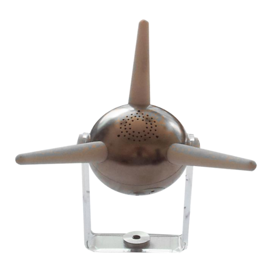
Page 6: General Information
1.1. Introduction Figure 1 The SEP was developed to selectively monitor the electric field in a very wide range and with a dynamic that is over 80 dB typically. Moreover, its data transmission system, made of non-conductive fiber optic, increases its performances and accuracy to perform measurements. -
Page 7: Option Wifi And Bluetooth Connection
- 4x Lithium battery: Panasonic model NCR18500 - Cap remover - User Manual - STD Calibration Certificate Option WiFi and Bluetooth connection For more information see APPENDIX B SEP Overview USB connector Status LED Fiber Optic ON/OFF button Figure 2... -
Page 8: Technical Specifications
USER MANUAL S E M S Technical specifications Frequency Range Band1 100 kHz to 9.999 MHz Band2 10 MHz to 3.6 GHz Resolution 1 kHz Reference Frequency Aging year 1 x 10 Temperature drift (0° C to + 30° C) 5 x 10 Frequency Span Range... - Page 9 USER MANUAL S E M S Flatness @ 0.5 to 10 MHz ± < 1 dB @ 50 v/m @ 10 to 2000 MHz ± < 1 dB @ 6 v/m @ 2 to 3 GHz ± < 1,2 dB @ 6 v/m @ 3 to 3.6 GHz ±...
-
Page 10: Software Specifications
USER MANUAL S E M S Software Specifications Scale Linear or semi-logarithmic Data Acquisition X,Y,Z selectable Measurements Marker �� ���� Dragged marker with value V/m; W/ ; mW/ ; mV/m Limit (Horizontal Marker) Select the peaks over the selectable limit. Orderable in frequency/amplitude Isotropic Root Mean Square value. -
Page 11: Operating Principle
PC. Through the PC software MPB SEP, users will be able to view real-time data while making measurements of revealed intensity point by point, read the values integration over a frequency band and save the work session as an image or data files, for a future check. -
Page 12: Sep Use And Operations
3.1. Power supply Figure 4 Cap Remover The SEP does not need external supply. It in fact uses two 3.7V lithium batteries, 49.3 mm long and 18.4 mm of diameter. This model (NCR18500) is manufactured by Panasonic. The batteries compartments are located on the side of the device, that can Errore. -
Page 13: Placement
To turn on the device, press the power button ON/OFF, shown in Figure 2 To turn it off press the same button for around 4 seconds. Please remember that the SEP is not a standalone device, so it has to be plugged to a PC for programming and for real-time data visualization. -
Page 14: Use And Functioning Of The Software Mpb Sep
Even the USB – RS232 converter, used to connect, through the fiber optic, the SEP to the PC, can be installed through the automatic functionality of the Windows driver research or, in case of no internet connection, using the manual installation mode of the driver, also provided in the USB key supplied. -
Page 15: Ftdi Driver Installation
(Figure 6(e)). Keeping the default settings, it will be possible to find the application installed on the smart menu, in the “MPB S.r.l.” folder. (a) Welcome... - Page 16 USER MANUAL S E M S (c) Link (d) Report (e) End Figure 6 Installer MPB SEP - 16 -...
-
Page 17: Software Home Page
By pressing the “Connect” button, the software will attempt a connection with the device, automatically finding the correct COM port. In case of eventual error message, the software will warn the user asking to check the power status of the SEP or the driver installation. -
Page 18: Standards And Limits
S E M S 4.5.1. Standards and Limits Through this form, that can be opened even when the SEP is not connected, the user can create standard files that the software will use to set limits and make measurements according to those limits. The default standards in the software are four: ... -
Page 19: Spectrum Mode
Figure 9 Persona Database 4.6. Spectrum Mode Once the SEP is connected, by selecting the “Spectrum Mode”, the scan will begin: on top left, you will find first the MPB logo, then battery status, the voltage and fans status. - 19 -... -
Page 20: Graphics
USER MANUAL S E M S Figure 10 MPB SEP Spectrum Mode 4.6.1. Graphics To the right of the battery indicator, the “Graphics” button is shown. By clicking “Graphics”, a panel is shown (as in Figure 11 Graphics Panel) giving the user the possibility to edit the view. -
Page 21: Snapshot
From this panel, the user can select which data source the software will use. During the first use, the selected data source will be the “SEP”, showing the connection status, as it is in the home page. Also as in the home page, from this tab is possible to connect or disconnect the SEP. -
Page 22: Registration
4.8. Registration Figure 15 SEP live bar Once the SEP is connected and operative, the lower part of the graph can be used for post processing operations. During the work session it is possible to pause the scan through the “Pause” button. The software has three record modes, that can be selected from the first panel after the record button. -
Page 23: Review Stored Session Files
USER MANUAL S E M S Figure 16 Level Triggered Recording 4.9. Review Stored Session Files From the Data Source panel, select the “Files” Data Source (Shown in Figure 13 Data ). This operation will change the control bar under the chart and the “Data source Source”... -
Page 24: Fast Configuration
USER MANUAL S E M S In the Data Source panel, by right clicking a file, a context menu will allow the user to load, export or delete each file. External files can be loaded by pressing the “Import” button over the three view tab. 4.10. - Page 25 USER MANUAL S E M S Figure 19 Manage Configurations - 25 -...
-
Page 26: Hw Options
Please note that, only for “Band1”, RBW value is fixed on 3 kHz and cannot be chosen. The SEP has six different filters: 1 MHz... - Page 27 USER MANUAL S E M S 300 kHz 100 kHz 30 kHz 10 kHz 3 kHz In the middle is the “Hardware Detector”: this panel allows choosing from three different modes of acquiring the single point within “Peak”, “Average” and “RMS”. In the bottom part, the “Hold Time”...
-
Page 28: Frequencies
USER MANUAL S E M S 4.12. Frequencies Through this tab, the user can insert and edit specific frequencies. Four commands are available: “Start”, “Stop”, “Span”, and “Center”. By editing values in any space provided, of course different values in the other three might appear. - Page 29 USER MANUAL S E M S On the left of frequency tab, the “Axis Selection” is available for the user to choose which axis to view. The ongoing axis will be “colored”. Please note that choosing the isotropy each axes will be enabled, even if not necessary visualized.
-
Page 30: Measurement Tools
USER MANUAL S E M S 4.14. Measurement tools In this section will be explained how to use all measurement tools in the software. Please note that these tools will work independently from the chosen data source. (Chapter 4.7) 4.14.1. Markers The “Markers”... -
Page 31: Multi Channel Power - Only In Band2
USER MANUAL S E M S 4.14.2. Multi Channel Power – Only in Band2 Figure 26 Multi Channel Power(1) The “Multi Channel Power (MCP)” allows performing the calculation of the values of the integrated field of more frequency ranges at once. In the current software version are allowed up to 50 channel powers in the same scansion. - Page 32 USER MANUAL S E M S the start to the bandwidth, set in the top part of the control. The CP later added will start from the stop of the previous one. Assuming the case where the span of the scansion is of 40 MHz, and the width of the CP to add is 80 MHz, only by activating 5 CP it will be possible to divide the whole scansion in 5 measuring bands.
- Page 33 USER MANUAL S E M S otherwise the value will be zero. Under the “Shown Values” command, there is the “Standard” field: by default the software will select “Flat Selectable Limit”, giving the user an additional control to define the amplitude limit. Moreover, the “Limit” tab can show on the graph the limits required by the different ongoing standards.
- Page 34 USER MANUAL S E M S The aim of this form is a calculation of the contribution of each source with respect to the applicable limits, described in the Italian D.P.C.M. of 07/08/2013, regarding the conformity reduction in accordance with the broadcast stations. The contribution is described by the following formula: ��...
-
Page 35: Appendix A Communication
Commands Description IDN? This command *IDN? gives version and date of the firmware, followed by [0D][0A] Example of reply: IDN=SEP-FW - B.37 20/10/17[0D][0A] For a correct configuration of the units use in this sequence the command setting: *IDN? SENS:FREQ:STOP:<value of frequency>... - Page 36 USER MANUAL S E M S PROPRIETARY REQUEST COMMANDS Commands Description CFG? This command *CFG? Gives the serial number and the calibration date, followed by [0D][0A] Reception Example: 001_160616 where: = serial number = separation special character 160616 = ddmmyy calibration date STA? This command *STA? Gives the status of the machine in a string containing: Vbat 4054mV;TBD;TBD;TBD;Ric 0;USB 1;Temp 0gr;Fun 0<0D><0A>...
- Page 37 USER MANUAL S E M S Every command is followed by CR+LF (CR = 0x1Dh ; LF = 0x0Ah) SENS:FREQ:STAR:150e3\r\n If in the following tab, that describes the syntax, a layer is not validated, the relative field will be omitted SENS:BAND:AUTO\r\n Syntax: Frequency setting:...
- Page 38 USER MANUAL S E M S Detector setting Level 1 Level 2 Level 3 SENS DETE PEAK Hold Time Setting Level 1 Level 2 Level 3 SENS HOLD Hold Time Value expr. in mSec minimum 10 maximum 10000 SENS:HOLD:1500 // set the Hold Time at 1.5 seconds Axis Setting Level 1...
- Page 39 USER MANUAL S E M S After being given a DATA:ISTA:VERB command, the apparatus transmits the samples in the following format: Fstart <start_value> Hz,Fstop <stop_value> Hz,Fstep <step_value> Hz,N level <levels number>,dBuV/m=><0D><0A> <data1>;<data2>;...<data n> Where: <start_value> = string containing the Hz value of the start frquency <stop_value>...
- Page 40 USER MANUAL S E M S Send string SENS:DETE:RMS\r\n 5. Set hold time Send string SENS:HOLD:0.5\r\n 6. Select axis Send string SENS:AXIS:X\r\n 7. Enable transmission of data acquisition Send string DATA:ISTA:VERB\r\n NOTE: The stop frequency will always have to be greater than start frequency +100 KHz, being 100 KHz the minimum settable span In the example, sending the commands that are summarized below, wait for each one to reply.
-
Page 41: Appendix B Wifi And Bluetooth Connection
S E M S 6. APPENDIX B WiFi and Bluetooth connection Figure 29 With the SEP it is possible to make remote measurements, via communication protocol (see APPENDIX A), and the use of the WiFi or bluetooth Option SEP_WLD: - Device SEP_WLD-WHD... -
Page 42: Wifi Connection (Mod. Sep-Whd)
- Connect USB – serial adapter to PC - Wait for green led named “Ready” and WLAN. The 4 green leds indicate the level of radio WiFi signal. (see Figure 30) - Run MPB-SEP program and select “connect to device”. Figure 30 - 42 -... -
Page 43: Bluetooth Connection (Mod. Sep-Wld)
USER MANUAL S E M S 6.2. Bluetooth connection (mod. SEP-WLD): In the bar status, select “Bluetooth and other devices” Figure 31 Then, “Add Bluetooth or other device”: Figure 32 - 43 -... - Page 44 USER MANUAL S E M S Select Add a device Bluetooth Figure 33 Select “RNBT-xxxx”: - 44 -...
- Page 45 USER MANUAL S E M S Figure 34 Accept the bluetooth association by clicking on “connect”: Figure 35 - 45 -...
-
Page 46: How To Verify Serial Port
USER MANUAL S E M S “ready for use” message is shown: Figure 36 6.3. How to verify serial port In bluetooth setting: a) click on “RNBT-xxxx” devices, b) click on “other Bluetooth option”, c) click on “port com”, d) read the COM number (e.g. COM7) with description “on OUT”... - Page 47 USER MANUAL S E M S Figure 37 - 47 -...
- Page 48 USER MANUAL S E M S Further information: www.gruppompb.uk.com Technical information: assistenza@gruppompb.com Phone +39 06 41200744 - 48 -...
Need help?
Do you have a question about the SEP and is the answer not in the manual?
Questions and answers