
Related Manuals for GE Oil & Gas Mooney Pilots 20 Series

Summary of Contents for GE Oil & Gas Mooney Pilots 20 Series
- Page 1 GE Oil & Gas Mooney* Series 20/20S/20H/20HS Pilots Instruction Manual GE Data Classification : Public...
- Page 2 THESE INSTRUCTIONS PROVIDE THE CUSTOMER/OPERATOR WITH IMPORTANT PROJECT- SPECIFIC REFERENCE INFORMATION IN ADDITION TO THE CUSTOMER/OPERATOR’S NORMAL OPERATION AND MAINTENANCE PROCEDURES. SINCE OPERATION AND MAINTENANCE PHILOSOPHIES VARY, GE (GENERAL ELECTRIC COMPANY AND ITS SUBSIDIARIES AND AFFILIATES) DOES NOT ATTEMPT TO DICTATE SPECIFIC PROCEDURES, BUT TO PROVIDE BASIC LIMITATIONS AND REQUIREMENTS CREATED BY THE TYPE OF EQUIPMENT PROVIDED.
-
Page 3: Table Of Contents
Scope This manual provides installation, operation and maintenance instructions for the Mooney Series 20/20S/20H/20HS Pilots. The manual is divided into the following sections: Contents Product Description................. 3 Piping Schematics ................6 Materials of Construction ............. 4 Installation ..................7-8 Specifications .................4-5 Maintenance ................8-12 Pilot Markings .................. -
Page 4: Materials Of Construction
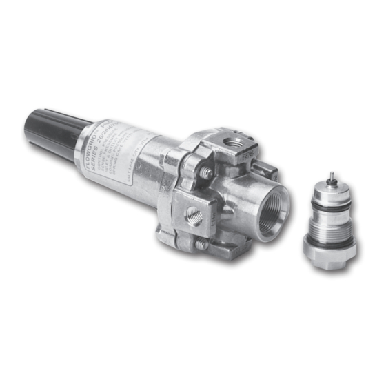
Sensing Port (4): The Series 20 Pilot has separate SENSE and OUTLET connections. The SENSE connection is “static” which means that there is no flow in the sensing line and the true pipeline pressure is measured at the diaphragm. Outlet Port (5): The OUTLET port must be connected to the valve outlet or outlet pressure system. -
Page 5: Pilot Markings
Table 4 Specifications Series Spring Range Color Part Number 3 - 12 psi (0.2 - 0.8 bar) 040-014-01 10 - 40 psi (0.7 - 2.7 bar) Plated 040-011-01 25 - 90 psi (1.7 - 6.2 bar) Blue 040-012-01 20 & 20S 60 - 200 psi (4 - 14 bar) Purple 040-008-01... -
Page 6: Piping Schematics
Series 20 Pilot – Piping Schematics - Unloading and Loading Type Valves Figure 6 Figure 7 Unloading Type Valve (Pressure Reducing Valve) Unloading Type Valve (Back Pressure Valve) Figure 8 Figure 9 Loading Type Valve (Pressure Reducing Valve) Typical Top View ©... -
Page 7: Installation
Series 20 Pilot – Unloading and Loading Type Valve Installation 1. PERSONNEL: Installation of the Series 20 Pilot on the WARNING Flowgrid Valve or any other manufacture’s valve should Personal injury, equipment damage, leakage or be made by qualified personnel familiar with explosion of accumulated gas or bursting of pressure high-pressure piping and Pilot-operated Regulators. -
Page 8: Maintenance
Use Table 5 as a guide for the ideal tubing to use. NOTE: A shutoff valve is not required in the supply to Reduce as necessary to connect to the pilot. the pilot, but if one is installed it should be a full NOTE: The control line connection should be 8-10 pipe opening type. - Page 9 Maintenance (cont’d) 5. Pilot Diaphragm: Release all Main Spring tension by unscrewing Adjusting Screw. Remove Closing Cap, Spring Follower, and Main Spring. Remove Spring Housing Cap Screws and remove Diaphragm Assembly. Disassemble Diaphragm Assembly and inspect Diaphragm. Replace if necessary. Figure 14 Placing the Spring Housing on the Pilot Body.
- Page 10 Maintenance (cont’d) 6B. PILOTS WITH BLACK AND GREEN SPRING: Install Closing Cap with Adjusting Screw, Spacer, Sealing Nut, and O-Ring. The spacer prevents the Black and Green springs from being over compressed. No Spacer Spacer Figure 19 Stack the Return Spring, Stem Guide, Orifice Spring, Plug and Stem, Orifice, Orifice O-Ring, and Back-up Washer on the Bottom Cap.
- Page 11 Maintenance 11. Insert Body Insert into Pilot Body and screw into (cont’d) place snugly. Pilot Assembly - Series 20 & 20S (cont’d) Stem O-Ring Figure 23 Figure 21 Insert Body Insert (Cartridge) with lubricated Stem In the back pressure mode the Plug and Stem assembly O-Ring into the Pilot Body is inverted.
- Page 12 Maintenance (cont’d) Pilot Assembly - Series 20H & 20HS (cont’d) 6. Follow assembly directions for Series 20 & 20S 2. Place Diaphragm Assembly in the pilot body with the Pilot for steps 6B through 10. Note the exception diaphragm touching the grooved sealing surface of to Step 7 for the Series 20H &...
-
Page 13: Warranty
Limited Warranty Seller warrants that Products shall be delivered free from defects in material, workmanship and title and that Services shall be performed in a competent, diligent manner in accordance with any mutually agreed specifications. The warranty for Products shall expire one (1) year from first use or eighteen (18) months from delivery, whichever occurs first, except that software is warranted for ninety (90) days from delivery. - Page 14 DIRECT SALES OFFICE LOCATIONS AUSTRALIA ITALY SOUTH AFRICA Brisbane: Phone: +39-081-7892-111 Phone: +27-11-452-1550 Phone: +61-7-3001-4319 Fax: +39-081-7892-208 Fax: +27-11-452-6542 Fax: +61-7-3001-4399 JAPAN SOUTH & CENTRAL Perth: Tokyo AMERICA AND THE CARIBBEAN Phone: +61-8-6595-7018 Phone: +81-03-6871-9008 Phone: +55-12-2134-1201 Fax: +61 8 6595-7299 Fax: +81-03-6890-4620 Fax:...