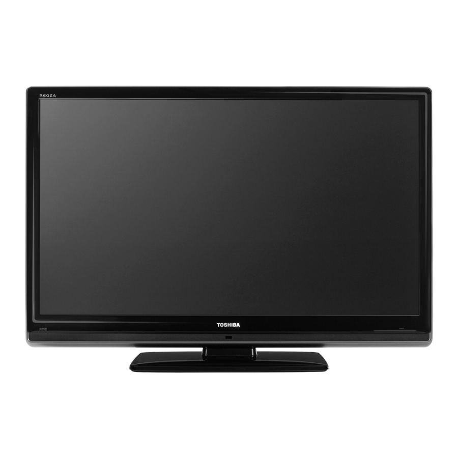
Toshiba 46RV530U Service Manual
Lcd color television
Hide thumbs
Also See for 46RV530U:
- Specifications (2 pages) ,
- Owner's manual (78 pages) ,
- Owner's manual (69 pages)
Advertisement
Quick Links
SERVICE MANUAL
For Technical Bulletins, Technical Tips, or other information regarding the
service of this model, visit the Toshiba America Consumer Products National
Service Division website at:
This model is classified as a
This Service Manual describes replacement parts for the green product. When repairing this
green product, use the part(s) described in this manual and
For (*1) and (*2), refer to
SOLDER.
© TOSHIBA CORPORATION 2008
LCD Color Television
46RV530U
www7.toshiba.com
green product
(*1), as indicated by the underlined serial number.
GREEN PRODUCT PROCUREMENT
Rev.1
lead-free solder
(*2).
LEAD-FREE
and
Advertisement

Subscribe to Our Youtube Channel
Summary of Contents for Toshiba 46RV530U
- Page 1 SERVICE MANUAL LCD Color Television 46RV530U Rev.1 For Technical Bulletins, Technical Tips, or other information regarding the service of this model, visit the Toshiba America Consumer Products National Service Division website at: www7.toshiba.com This model is classified as a green product (*1), as indicated by the underlined serial number.
- Page 2 EXPRESS OR IMPLIED WARRANTY OF MERCHANTABILITY AND FITNESS FOR A PARTICULAR PURPOSE. Toshiba shall not be liable for any damages, losses, expenses or costs, if any, incurred in connection with or as a result of use of any information or data provided herein.
- Page 3 that have these same characteristics. Use only the specified parts when the mark is indicated in the circuit diagram or parts list. Part mounting and wire routing should be the same as that used originally. For safety purposes, insulating materials such as isolation tubes or tape are sometimes used and printed circuit boards are sometimes mounted floating.
- Page 4 fluid should contact the skin or clothing, wipe off with alcohol, etc., and rinse thoroughly with water. If the fluid should enter the eyes, immediately rinse the eyes thoroughly with running water. When attaching the LCD module to the LCD cover, position it appropriately and fasten at the position where the display can be viewed most conveniently.
- Page 5 CMOS-LSI circuitry is used in the LCD module, so avoid damage due to static electricity. When handling the module, use a wrist ground or anchor ground. Do not expose the LCD module to direct sunlight or strong ultraviolet rays for extended periods. Do not store the LCD module below the temperature conditions described in the specifications.
- Page 6 Entering Service Mode Set VOLUME to minimum and press MUTE button twice on the remote control. ↓ Press MUTE button again and hold button down. ↓ Service Mode display While holding the MUTE button, press MENU button on TV set. Selecting the Adjusting Item Every pressing of CH button in the service mode changes the adjustment items.
- Page 7 Firmware Update Process Updating this chassis family is accomplished using an SD card furnished by Toshiba. With the unit operating, insert the card into the card slot labeled “Service only” located on either the side or back of the instrument. After the card is inserted, simply follow the step by step update instructions displayed on the screen.
- Page 9 46RV530U Power Distribution and Plug Layout 1. 24V 2. 24V 3. 24V 4. 24V 5. 24V 6. GND 24V Inverter Supplies 7. GND 8. GND 9. GND 10. GND LVDS Inverter 1. GND P861 2. 5V1< CN60 CN61 3. GND...
- Page 10 Dead Does 3.2 volts appear at pin 8 of P810 on the power board when on/ off is pressed? Does 24 volts appear at 5 volts present at pin 2 pin 1-5 of P860 on the of P811 as soon as AC power board when on/ is applied? off is pressed?
- Page 11 *** Contact Toshiba at www7.tacp.com for warranty authorization If the LCD Control Picture Board is available, try Problems it. If this does not help, Examples replace the LCD display panel. *** Does the screen discolored the back light function or does it have streaks...
- Page 12 (P)* - 46 and 52 inch display. *** P860 and P861 when RV models contain a P- the unit is turned power supply module. Replace the *** Contact Toshiba at (P)* Power Is 12VDC www7.tacp.com for supply present at pins 1 module.
- Page 13 Sound Problems Distorted No Sound Is there no sound or is the audio distorted? If the input selection is changed, does audio appear? Problem solved. Is 18VDC present at pin 13 of P811A when the unit is turned on? Suspect the *P811A is located on Replace the (S)* power...
-
Page 14: Parts List
PARTS LIST Precaution WARNING: BEFORE SERVICING THIS CHASSIS, READ THE "X-RAY RADIATION PRECAUTION" FOR DIRECT VIEW CTV ONLY, "SAFETY PRECAUTION" AND "PRODUCT SAFETY NOTICE" OF THIS MANUAL. CAUTION: The international hazard symbols " " in the schematic diagram and the parts list designate components which have special characteristics important for safety and should be replaced only with types identical to those in the original circuit or specified in the parts list. - Page 15 75011245 DISPLAY , LTA460HB07 LCD Panel A201 75011247 FRONT BEZEL ASSY 46RV530U, FRONT Cabinet Front A401 75011248 BACK COVER ASSY 46RV530U, BACK COVER Cabinet Back A420 75010936 LEG STAND LEG ASSY, STAND LEG ASSY 42RV500 Stand Leg A421 75010935 BASE BASE ASSY, BASE ASSY 42RV500...
- Page 16 TOSHIBA CORPORATION 1-1, SHIBAURA 1-CHOME, MINATO-KU, TOKYO 105-8001, JAPAN...


Need help?
Do you have a question about the 46RV530U and is the answer not in the manual?
Questions and answers
Is there a reset button, tv will not come on