
Related Manuals for MuginUAV MUGIN-2 2930 VTOL


Summary of Contents for MuginUAV MUGIN-2 2930 VTOL
- Page 1 MUGIN VTOL UAV ( Electric Setup ) BUILD GUIDE V1 MUGIN-2 2930 VTOL MUGIN-2 PRO 2930 VTOL MUGIN-3 PRO 3000 VTOL MUGIN-4 PRO 4000 VTOL Copyright © 2019 Mugin Tech Ltd.
-
Page 2: Safety And Warning
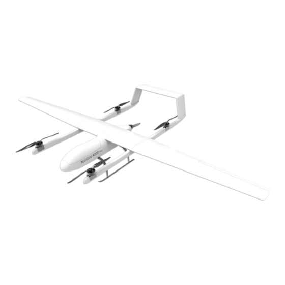
This gives the aircraft the ability to take off and land vertically, it also has the ability to transition to forward flight like a fixed wing. This hybrid configuration combines the advantages of VTOL and high speed, long endurance flights of a fixed wing. Copyright © Mugin Tech Ltd www.muginuav.com sales@muginuav.com... - Page 3 Left rear boom Left landing skid Right front Right landing boom skid Right rear Forward landing boom arch Rear landing Left wing arch Main Forward Right wing Carbon Spar Rear Carbon Rear elevator Spar Fuselage Copyright © Mugin Tech Ltd www.muginuav.com sales@muginuav.com...
-
Page 4: Power System
Below is a power system that we have selected and is available for optional purchase. Description Picture Savox SC-1251MG Low Profile Digital Servo x 6 T-motor MN805-S KV170 (VTOL Motors) x 4 T-motor Flame 80A HV ESC x 4 Copyright © Mugin Tech Ltd www.muginuav.com sales@muginuav.com... - Page 5 Motor Mount for VTOL Thrust Motors Main Power Wires for Electric Motors Main Power Wires for PDB 22A Silicone power lines Servo Extension Wires Servo extension connectors D-Sub connectors 2x 15pin, 1x 24pin Copyright © Mugin Tech Ltd www.muginuav.com sales@muginuav.com...
- Page 6 50.4v Voltage Regulator to 6v Falcon PAE 24″ Propeller (Pairs) x 2 Falcon C2E 21″ Propeller x 1 * Due to the stock availability, the listed items are subject to change without prior notice. Copyright © Mugin Tech Ltd www.muginuav.com sales@muginuav.com...
-
Page 7: Power System Installation
Mugin airframes are very DIY in nature. Before attempting to build, please make certain you and your team have the required experience and skill set that is needed in order to build a model such as this. Pictured above is a rough layout for the optional power Package. Copyright © Mugin Tech Ltd www.muginuav.com sales@muginuav.com... -
Page 8: Servo Installation
1. Beginning with servo installation in the elevator. Take two Savox servos and install in the cutouts. Before attempting to install control horns servos should be tested and centered to prepare for proper control placement. Copyright © Mugin Tech Ltd www.muginuav.com sales@muginuav.com... - Page 9 Copyright © Mugin Tech Ltd www.muginuav.com sales@muginuav.com...
- Page 10 Picture 1 shows the the Rudder Servo (A) and the extension wire for Elevator Servo (B). Picture 2 shows the extension wire connected. Remember to give yourself enough wire length to exit the large opening in the center of the boom. Copyright © Mugin Tech Ltd www.muginuav.com sales@muginuav.com...
- Page 11 Picture 3 shows the layout of the wiring before servo installation. 3. Aileron Servo Installation: The aileron servo installation is a relatively easy process. If using D-Sub connectors remember proper wiring placement to avoid reverse polarity issues. Copyright © Mugin Tech Ltd www.muginuav.com sales@muginuav.com...
- Page 12 Once again, remembering the wiring sequence of the D-Sub connectors to avoid reverse polarity issues. The D-Sub connectors can be attached using aluminum rivets.(2A). Copyright © Mugin Tech Ltd www.muginuav.com sales@muginuav.com...
-
Page 13: Motor Installation
If you have purchased a Mugin in the past and would like a 3D printed cutting guide, please send us a message to sales@muginuav.com . The process is straight forward and can use the following 5 steps to complete the process. - Page 14 Copyright © Mugin Tech Ltd www.muginuav.com sales@muginuav.com...
- Page 15 Picture 6(A1): Connect the motor to ESC (A1),ESCs to power extension wires, install extension wires for servo.(A2) Copyright © Mugin Tech Ltd www.muginuav.com sales@muginuav.com...
- Page 16 When installing the ESC everyone has their own methods. The one we use is to run the double sided tape down the bottom facing edge of the ESC and use blue foam on the outside surfaces to help with vibrations. Please refer to B1 and B2. Copyright © Mugin Tech Ltd www.muginuav.com sales@muginuav.com...
- Page 17 After completing the installation of the ESC, the Motor is now free to be mounted. C1 and C2 Copyright © Mugin Tech Ltd www.muginuav.com sales@muginuav.com...
- Page 18 ESCs and six servos. Having a clear plan at this point is a must but if you follow the steps above, it won't be too complicated. Copyright © Mugin Tech Ltd www.muginuav.com sales@muginuav.com...
- Page 19 Some clients mount it in the fuselage. You are free to do as you please. We are going with this method on this one by cutting out a slot to mount it to the interior of the center wing. Copyright © Mugin Tech Ltd www.muginuav.com sales@muginuav.com...
- Page 20 Once the slot is cut out we’ve routed the wires through the center of the wing and now have the main wiring harness on the interior. Copyright © Mugin Tech Ltd www.muginuav.com sales@muginuav.com...
- Page 21 The below picture shows how the 25pin D-Sub connector mounts on the fuselage. The female connector in mounted on the center wing. Copyright © Mugin Tech Ltd www.muginuav.com sales@muginuav.com...
- Page 22 Mounting the motor to the Motor mount is very straight forward. You will have that accomplished in no time by looking at the below picture. Once the motor is mounted to the motor mount, place the shroud over the motor and determine where the motor is centered. Copyright © Mugin Tech Ltd www.muginuav.com sales@muginuav.com...
- Page 23 The ESC doesn’t have to be as precise but it is nice to have a clean looking build. Take the time to lay the ESC out in a nice looking position and mark holes too. Copyright © Mugin Tech Ltd www.muginuav.com sales@muginuav.com...
- Page 24 Installing the ESC and Motor Once you reach this point it’s just a matter of drilling the holes and mounting the two devices. Copyright © Mugin Tech Ltd www.muginuav.com sales@muginuav.com...
- Page 25 In the package you’ll find a small bag that has a label on it. This is also a straight forward process. Copyright © Mugin Tech Ltd www.muginuav.com sales@muginuav.com...
- Page 26 At this point, the installation of the aircraft power equipment is completed, and the following is to assemble the aircraft. Here is a general overview of the assembly. Copyright © Mugin Tech Ltd www.muginuav.com sales@muginuav.com...
-
Page 27: Boom Assembly
Boom Assembly This will be mounted to the underside once the outer wing is installed. Copyright © Mugin Tech Ltd www.muginuav.com sales@muginuav.com... - Page 28 The elevator is a dual redundant elevator. The elevator has been split in half, composing of two sections. If one servo fails, the other half of the elevator can still control altitude movements. Copyright © Mugin Tech Ltd www.muginuav.com sales@muginuav.com...
-
Page 29: Aileron Assembly
Aileron Assembly There are two spars, the main spar and the secondary spar. These will slide through the center wing. Copyright © Mugin Tech Ltd www.muginuav.com sales@muginuav.com... -
Page 30: Final Assembly
3. Do not worry about powering up after all equipment is installed. First, check whether the circuit is normal. In particular, do not connect the positive and negative poles (you can use the meter to detect) to avoid. Copyright © Mugin Tech Ltd www.muginuav.com sales@muginuav.com...
Need help?
Do you have a question about the MUGIN-2 2930 VTOL and is the answer not in the manual?
Questions and answers