Sign In
Upload
Download
Table of Contents
Contents
Add to my manuals
Delete from my manuals
Share
URL of this page:
HTML Link:
Bookmark this page
Add
Manual will be automatically added to "My Manuals"
Print this page
×
Bookmark added
×
Added to my manuals
Manuals
Brands
Terrasat Manuals
Media Converter
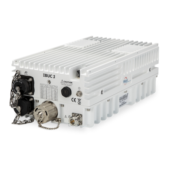
IBUC 2
Operation manual
Terrasat IBUC 2 Operation Manual
Cyber hardened intelligent block upconverter
Hide thumbs
1
2
Table Of Contents
3
4
5
6
7
8
9
10
11
12
13
14
15
16
17
18
19
20
21
22
23
24
25
26
27
28
29
30
31
32
33
34
35
36
37
38
39
40
41
42
43
44
45
46
47
48
49
50
51
52
53
54
55
56
57
58
59
60
61
62
63
64
65
66
67
68
69
70
71
72
73
74
75
76
77
78
79
80
81
82
83
84
85
86
87
88
89
90
91
92
93
94
95
96
97
98
99
100
101
102
103
104
105
106
107
108
109
110
111
112
113
114
115
116
117
118
119
120
121
122
123
124
125
126
127
128
129
130
131
132
133
134
135
136
137
138
139
140
141
142
143
144
145
146
147
148
149
150
151
152
153
154
155
156
157
158
159
160
161
162
163
164
165
166
167
168
169
170
171
172
173
174
175
176
177
178
179
180
181
182
183
184
185
186
187
188
189
190
191
192
193
194
195
196
page
of
196
Go
/
196
Contents
Table of Contents
Troubleshooting
Bookmarks
Table of Contents
Table of Contents
Preface
Conventions and References
Table P.1 Typographical Conventions
Cautions and Warnings
Electrical Safety Notice
Trademarks
Chapter 1, Introduction
Block Upconverters
Reference Documents
Table 1.1 Satellite Operation Standards
Warranty Information
Chapter 2, Functional Description
Introduction
System Components
Table 2.1 IBUC 2 Transmit Frequency Plans
Table 2.2 IBUC 2E Transmit Frequency Plans
Table 2.3 IBUC 2G Transmit Frequency Plans
Table 2.4 IBUC R Transmit Frequency Plans
Table 2.5 IBUC G Transmit Frequency Plans
AC Supply
DC Supply
Fuses
Table 2.7 Fuse Markings
Figure 2.5 IEC
Monitor and Control
RF Signal Flow
Figure 2.6 DC-Powered Low-Power Cyber Hardened IBUC Block Diagram
Figure 2.7 DC-Powered Cyber Hardened IBUC Block Diagram
Figure 2.8 AC-Powered Cyber Hardened IBUC Block Diagram
Software
System Configurations
Table 2.10 Basic System Requirements
Figure 2.9 DC Low Power IBUC System Configuration
Figure 2.10 DC Power IBUC System Configuration
Figure 2.11 AC Power IBUC System Configuration
Storage Information
Chapter 3, Installation
Introduction
General Requirements
Unpacking
Furnished Items
Accessories
Installing the ODU
Test Equipment
Site Considerations
Mounting Considerations
Table 3.1 Recommended Test Equipment
Power Requirements
Table 3.2 Terrasat Outdoor Power Supplies
Grounding
Antenna Recommendations
Antenna Mounting
Figure 3.2 IBUC 2 Field Installation
Figure 3.3 IBUC 2 Installation
Figure 3.4 Location of Mounting Holes
Figure 3.5 IBUC in Line Mounting Configuration
System Pressurization
Figure 3.6 Location of Adjustment Slots on Optional Mounting Bracket
System Cabling Requirements
Figure 3.7 Connector J1 Caution Symbol
Table 3.4 Pin Assignments for M&C Interface Connector J2
Table 3.5 Pin Assignments for DC Power Connector J3
Table 3.6 Pin Assignments for AC Power Connector J3
Table 3.7 Pin Assignments for Milspec High-Power AC Connector J3
Table 3.8 Pin Assignments for Ethernet Connector J4
Cable and Waveguide Connections
Figure 3.8 Applying the Anti-Seize Lubricant
Basic System Alignment
Figure 3.9 Waveguide Label and Channel for Gasket
Setting the Tx and Rx Frequencies
Transmit Power Alignment
Transmit RF Output Adjustment with Modem or Converter (70 Mhz to L-Band)
Final Checks
Chapter 4, Operations
Introduction
Start-Up Checklist
Turning on the IBUC
Setting Operating Parameters
Setting the Tx Frequency (L-Band)
Setting Alarm Thresholds
Configuring Alarm States
Configuring ALC/AGC
Configuring the External Mute
Common Errors
LED Is Red
No Power to the Cyber Hardened IBUC 2, IBUC 2E, IBUC 2G, IBUC R or IBUC G
Time Stamp Data Is Incorrect
Satellite Network Operations Center Doesn't Recognize Signal
Transmit Power in Saturation
Tx Input/Output Level Verification
Chapter 5, Monitor and Control Features
Introduction
M&C Interfaces
Rs232
Multifunction LED
Ethernet
Table 5.1 Default Alarm Configuration
Determining the IP Address of Your IBUC
Sshv2
Snmpv3
Embedded Web Pages
Power Measurement
Input Power Overdrive Protection
Chapter 6, Troubleshooting
Maintenance
Transceiver Fault Isolation
AC Power Problems/Conditioning
Site-Related Problems
M&C Checks
Power Supply Checks
Transmit Power Setting
Common Problems
Tx Output Is Disabled
Incorrect Frequency Settings
Damaged Cables
10 Mhz Reference Signal Is at the Wrong Level or Missing
Antenna Is Pointed Toward Wrong Satellite or Is Misaligned
Table 6.1 Possible Scenarios for Ibucs with an External 10 Mhz Reference Signal
Moisture Migrated into the Cyber Hardened IBUC
Bad Orthogonal Mode Transducer And/Or Antenna
LED Is Red
Repair Policy
Returned Material Authorization (RMA)
Appendix A, Part Numbering Schema
Identifying the Part and Serial Numbers
Decoding the Part Number
Figure A.1 Identifying the Part and Serial Numbers
Figure A.3 Part Numbering Schema for Cyber Hardened IBUC with PSUI Systems
Appendix B, Embedded Web
Introduction
Figure B.1 Ethernet Properties Window
Figure B.2 Choosing the Internet Protocol (TCP/IP) Properties
Figure B.3 Host IP Address Configuration
Screen Shots
Responsive Design
Information Tab
Alarm Tab
Figure B.7 Alarm Status Tab
Sensor Tab
Figure B.8 Sensor Tab
Transmit Configuration Tab
Figure B.9 Tx Configuration Tab
Table B.1 Default Values for Power Monitor Frequency
Table B.2 Default Values for Burst Threshold
Interface Configuration Tab
Figure B.10 Interface Configuration Tab
System Configuration Tab
Figure B.11 System Configuration Tab
Alarm Configuration Tab
Figure B.12 Alarm Configuration Tab
Charts
Figure B.13 Statistics Charts
Appendix C, ASCII Command/Response Structure
Cyber Hardened IBUC Console and Sshv2 Command Set
Table C.1 Error Response Table
Table C.2 Alarm Mask
Table C.3 Configurable Alarm Mask
Table C.4 Default Values for the TAH, TAL, and TBT Commands
Table C.5 Band Numbering
Appendix D, Component Specifications and Reference Drawings
Reference Drawings
Figure D.1 Fabrication Drawing, FBD-21012-XXXX, Rev a
Figure D.4 Fabrication Drawing, FBD-20606-XXXX, Rev a
Figure D.5 Example Installation Drawing, IND-10521-0011, Rev a
Data Sheets
Appendix E, Firmware Upgrade
Update Procedure
Figure B.6 Information Tab
Advertisement
Quick Links
Download this manual
Engineered to Endure
Cyber Hardened Intelligent Block
Upconverter
IBUC 2, IBUC 2e, IBUC 2G, IBUC R and IBUC G
Operations Manual
24-Hour Technical Support: +1 669.258.9740
Table of
Contents
Previous
Page
Next
Page
1
2
3
4
5
Advertisement
Table of Contents
Need help?
Do you have a question about the IBUC 2 and is the answer not in the manual?
Ask a question
Questions and answers
Related Manuals for Terrasat IBUC 2
Media Converter Terrasat IBUC R Operation Manual
Cyber hardened intelligent block upconverter (196 pages)
Media Converter Terrasat IBUC Operation Manual
Intelligent block upconverter (155 pages)
Media Converter Terrasat IBUC 3 Operation Manual
Intelligent block upconverter (236 pages)
This manual is also suitable for:
Ibuc 2e
Ibuc 2g
Ibuc r
Ibuc g
Table of Contents
Save PDF
Print
Rename the bookmark
Delete bookmark?
Delete from my manuals?
Login
Sign In
OR
Sign in with Facebook
Sign in with Google
Upload manual
Upload from disk
Upload from URL


Need help?
Do you have a question about the IBUC 2 and is the answer not in the manual?
Questions and answers