Table of Contents
Advertisement
Emergency Locator Transmitter
KANNAD 406 AF / AF-H / AF (6D)
P/N : S1821502-02
P/N : S1822502-02
P/N : S1821502-06
P/N : S1820511-01
Revision 16
First issue: SEP 02/1999
Orolia S.A.S.
INSTALLATION MANUAL
OPERATION MANUAL
KANNAD 406 AF transmitter
KANNAD 406 AF-H transmitter
KANNAD 406 AF(6D) transmitter
Mounting bracket, 1 strap
DMA174S
TP PAGE : 1
Date of rev. MAR 30/2020
Advertisement
Table of Contents

Related Manuals for Orolia KANNAD 406 AF

Summary of Contents for Orolia KANNAD 406 AF
- Page 1 DMA174S Emergency Locator Transmitter Orolia S.A.S. INSTALLATION MANUAL OPERATION MANUAL KANNAD 406 AF / AF-H / AF (6D) P/N : S1821502-02 KANNAD 406 AF transmitter P/N : S1822502-02 KANNAD 406 AF-H transmitter P/N : S1821502-06 KANNAD 406 AF(6D) transmitter P/N : S1820511-01...
- Page 2 Orolia S.A.S. This document is to be returned to the orolia group when the agreed purpose is fulfilled. © 2020 Orolia S.A.S. All rigths are strictly reserved.
- Page 3 INSTALLATION MANUAL OPERATION MANUAL KANNAD 406 AF / AF-H / AF (6D) RECORD OF REVISIONS REV. Nb REVISION DATE INSERTION DATE OCT 14/2003 OCT 14/2003 J. S. NOV 19/2003 NOV 19/2003 J. S. APR 23/2004 APR 23/2004 J. S. JAN 24/2005 JAN 24/2005 J.
- Page 4 INSTALLATION MANUAL OPERATION MANUAL KANNAD 406 AF / AF-H / AF (6D) RECORD OF REVISIONS PAGE INTENTIONALLY LEFT BLANK ROR PAGE: 2 © 2020 Orolia S.A.S. All rigths are strictly reserved. MAR 30/2020...
- Page 5 INSTALLATION MANUAL OPERATION MANUAL KANNAD 406 AF / AF-H / AF (6D) LIST OF EFFECTIVE PAGES SUBJECT PAGE DATE Title Page MAR 30/2020 Record of Revisions MAR 30/2020 MAR 30/2020 List of Effective Pages MAR 30/2020 MAR 30/2020 MAR 30/2020...
- Page 6 INSTALLATION MANUAL OPERATION MANUAL KANNAD 406 AF / AF-H / AF (6D) LIST OF EFFECTIVE PAGES SUBJECT PAGE DATE System Functional Description and Operation MAR 30/2020 MAR 30/2020 MAR 30/2020 MAR 30/2020 MAR 30/2020 MAR 30/2020 MAR 30/2020 MAR 30/2020...
- Page 7 INSTALLATION MANUAL OPERATION MANUAL KANNAD 406 AF / AF-H / AF (6D) LIST OF EFFECTIVE PAGES SUBJECT PAGE DATE Check MAR 30/2020 MAR 30/2020 MAR 30/2020 MAR 30/2020 Troubleshooting MAR 30/2020 MAR 30/2020 Schematics and Diagrams MAR 30/2020 MAR 30/2020...
- Page 8 INSTALLATION MANUAL OPERATION MANUAL KANNAD 406 AF / AF-H / AF (6D) LIST OF EFFECTIVE PAGES PAGE INTENTIONALLY LEFT BLANK LEP PAGE: 4 © 2020 Orolia S.A.S. All rigths are strictly reserved. MAR 30/2020...
-
Page 9: Table Of Contents
DIN-12 connector or programming dongles............6 ELT-NAV System Interface..................6 External antennas....................7 KANNAD 406 AF....................7 KANNAD 406 AF-H and KANNAD 406 AF(6D) ........... 7 SYSTEM FUNCTIONAL DESCRIPTION AND OPERATION ..... 101 Transmitter ..................101 Controls....................102 Working mode information ..............103 Off ........................ - Page 10 INSTALLATION MANUAL OPERATION MANUAL KANNAD 406 AF / AF-H / AF (6D) TABLE OF CONTENTS INSTALLATION / REMOVAL.............. 201 Registration and Programming ............201 Pin programming option ..................201 ELT and bracket installation............... 203 Installation recommendations................203 FAA Recommendations ................... 203 TSO C126a Section 5 b.
- Page 11 INSTALLATION MANUAL OPERATION MANUAL KANNAD 406 AF / AF-H / AF (6D) TABLE OF CONTENTS SCHEMATICS & DIAGRAMS ............. 501 Outline Dimensions................501 Drilling Mask ..................502 Wiring....................503 ANT AV200, outline dimensions and drilling mask ......504 ANT AV300, outline dimensions and drilling mask ......505 ANT560, outline dimensions and drilling mask ........
- Page 12 INSTALLATION MANUAL OPERATION MANUAL KANNAD 406 AF / AF-H / AF (6D) TABLE OF CONTENTS PAGE INTENTIONALLY LEFT BLANK TOC PAGE: 4 © 2020 Orolia S.A.S. All rigths are strictly reserved. MAR 30/2020...
-
Page 13: Introduction
INTRODUCTION The instructions in this manual provide the information necessary for the installation and the operation of KANNAD 406 AF, AF-H and AF (6D) ELTs. Servicing instructions are normally performed by shop personnel. For servicing and maintenance instructions, refer to relevant CMM. - Page 14 INSTALLATION MANUAL OPERATION MANUAL KANNAD 406 AF / AF-H / AF (6D) PAGE INTENTIONALLY LEFT BLANK PAGE INTRO 2 © 2020 Orolia S.A.S. All rigths are strictly reserved. MAR 30/2020...
-
Page 15: System Overview
INSTALLATION MANUAL OPERATION MANUAL KANNAD 406 AF / AF-H / AF (6D) SYSTEM OVERVIEW 1. COSPAS-SARSAT System A. Description Launched in the early eighties by the four founder countries (Canada, France, Russia, USA), the COSPAS-SARSAT system provides satellite aid to search and rescue (SAR) operations for maritime, aeronautical and terrestrial vehicles anywhere in the world. -
Page 16: World Coverage With The Cospas-Sarsat System
INSTALLATION MANUAL OPERATION MANUAL KANNAD 406 AF / AF-H / AF (6D) B. World coverage with the COSPAS-SARSAT system The major improvement is the use of the COSPAS-SARSAT system for processing aeronautical emergencies. The difference with the 121.5 / 243 MHz is that the 406 MHz transmission... -
Page 17: Kannad 406 Elts Presentation
ELT with a 4 or 5 wire bundle. Figure 2: ELT system description The KANNAD 406 AF and AF(6D) are designed to be installed on fixed wing aircraft or helicopters. The KANNAD 406 AF-H is to be installed only on helicopters. -
Page 18: Line Replaceable Units
3. LINE REPLACEABLE UNITS A. Transmitter The KANNAD 406 AF / AF-H / AF (6D) is an ELT designed to be installed on board aircraft to transmit a distress signal on 3 frequencies: • 406 MHz (COSPAS-SARSAT frequency) for precise pinpointing and identification of the aircraft in distress. -
Page 19: Design Features
KANNAD 406 AF / AF-H / AF (6D) 4. Design features A. General The KANNAD 406 AF / AF-H / AF (6D) belong to the AF type of ELTs which are permanently attached to an aircraft. B. Mechanical design The KANNAD 406 AF / AF-H / AF (6D) are made of moulded plastic with excellent mechanical resistance (ASA/PC, light yellow colour). -
Page 20: Compatibility List
INSTALLATION MANUAL OPERATION MANUAL KANNAD 406 AF / AF-H / AF (6D) 5. Compatibility list A. Remote control panels (RCP) Orolia Designation Orolia Part Number RC100 KIT S1820513-03 RC150 KIT S1820513-07 RC200 S1820513-11 RC200-NVG S1820513-14 RC300 S1820513-09 RC400 S1820513-05 RC500-320... -
Page 21: External Antennas
INSTALLATION MANUAL OPERATION MANUAL KANNAD 406 AF / AF-H / AF (6D) D. External antennas (1).KANNAD 406 AF Orolia Designation Manufacturer Orolia Part Number ROD ANTENNA AV300 RAMI AV-300 0146151 ROD ANTENNA ANT300 CHELTON 1327-82 0124220 BLADE ANTENNA ANT560 DAYTON GRANGER... - Page 22 INSTALLATION MANUAL OPERATION MANUAL KANNAD 406 AF / AF-H / AF (6D) PAGE INTENTIONALLY LEFT BLANK PAGE: 8 © 2020 Orolia S.A.S. All rigths are strictly reserved. MAR 30/2020...
-
Page 23: System Functional Description And Operation
(thanks to a shock sensor) or manually (thanks to a switch on the transmitter itself or on a Remote Control Panel). The KANNAD 406 AF / AF-H / AF (6D) are designed to transmit on three frequencies (121.5, 243 and 406 MHz). The two basic emergency frequencies (121.5 and 243 MHz ) are mainly used for homing in the final stages of the... -
Page 24: Controls
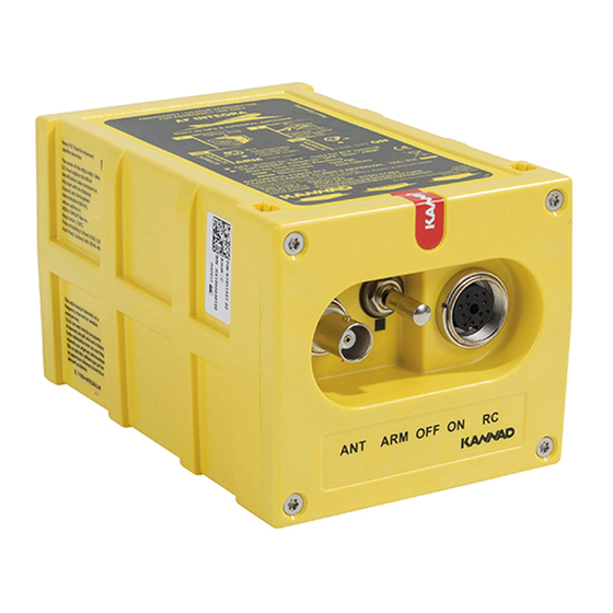
INSTALLATION MANUAL OPERATION MANUAL KANNAD 406 AF / AF-H / AF (6D) 2. Controls CAUTION: WHEN ACTIONING THE ARM/OFF/ON SWITCH, PULL LEVER TO UNLOCK AND SET TO POSITION. The following controls are to be found on the ELT front panel (from left to right): 3-position switch ARM/OFF/ON;... -
Page 25: Working Mode Information
INSTALLATION MANUAL OPERATION MANUAL KANNAD 406 AF / AF-H / AF (6D) 3. Working mode information The KANNAD 406 AF / AF-H / AF (6D) have 4 different modes: • Off. • Self-test (temporary mode). • Armed (standby mode to enable automatic activation by the shock sensor or by the remote control panel). - Page 26 INSTALLATION MANUAL OPERATION MANUAL KANNAD 406 AF / AF-H / AF (6D) aircraft is parked for a long period or for maintenance. The Remote Control Panel is energized by the ELT when the ELT’s Switch is in the "ARM" position.
-
Page 27: Endurance
INSTALLATION MANUAL OPERATION MANUAL KANNAD 406 AF / AF-H / AF (6D) 4. Endurance The energy is provided by a battery pack composed of 3 LiMnO D cells (See pages 107 & 602 for Kit battery reference). Lithium cells, lithium batteries and equipment containing such batteries are subjected to regulations and classified under class 9 as from 1st of January 2003. -
Page 28: Electrical Characteristics
INSTALLATION MANUAL OPERATION MANUAL KANNAD 406 AF / AF-H / AF (6D) 5. Electrical characteristics Transmitter power supply: 3 x LiMnO D type cells. A. Electrical interface When installed on board, the ELT has to be connected: • to a Remote Control Panel via a DIN12 connector;... -
Page 29: Technical Specifications
INSTALLATION MANUAL OPERATION MANUAL KANNAD 406 AF / AF-H / AF (6D) IMPORTANT : Cable with radio electric properties similar or better to those of a RG58 cable are recommended. 6. Technical Specifications TYPE CONTROLS • Three-frequency ELT • ARM / OFF / ON switch (121.5 / 243.0 / 406.025 MHz) -
Page 30: Activation
INSTALLATION MANUAL OPERATION MANUAL KANNAD 406 AF / AF-H / AF (6D) 7. Activation A. Standby mode for automatic activation In order to be automatically activated by the crash sensor, the ELT must be in standby mode. This mode is mandatory during the flight. We recommend to switch the ELT off only when the aircraft is parked for a long period or for a maintenance operation. - Page 31 Any change of ownership shall also be declared and registered with the local registration authority and with the distributor. The KANNAD 406 AF / AF-H / AF (6D) are fully compatible with the four programming protocols defined by the COSPAS-SARSAT C/S G005 document: •...
- Page 32 INSTALLATION MANUAL OPERATION MANUAL KANNAD 406 AF / AF-H / AF (6D) board the aircraft. When an unprogrammed ELT is installed and connected to this Programming Dongle and the "ELT" is switched to "ARM", it automatically updates its own memory with the identification data contained in the Programming Dongle memory.
- Page 33 INSTALLATION MANUAL OPERATION MANUAL KANNAD 406 AF / AF-H / AF (6D) 2. ELT and bracket installation A. Installation recommendations "The ELT shall not be installed within 60cm (2 ft) of a compass or flux gate. The distance between ELT and antenna shall be determined so that, according ≤...
- Page 34 INSTALLATION MANUAL OPERATION MANUAL KANNAD 406 AF / AF-H / AF (6D) B. Bracket installation • Determine the location of the ELT on board according to FAR/RTCA recommendations. CAUTION: DO NOT INSTALL THE ELT IN A LOCATION DIRECTLY EXPOSED TO THE SUN.
- Page 35 "Direction of Flight" label pointed towards the front of the aircraft. (b) Helicopters The KANNAD 406 AF can be installed in its standard version on helicopter. The ELT unit should be mounted: • with the front face connectors pointing downwards at a 45° angle to the yaw axis (with maximum tolerance of 15°);...
- Page 36 (and not pointing 45° downwards) with maximum tolerance of 15°: - If the KANNAD 406 AF-H is installed with the "Direction of Flight " arrow pointing towards the front of the helicopter, the ELT shall be mounted with the upper side pointing towards the top of the helicopter.
- Page 37 (3) KANNAD 406 AF (6D) installation Figure 205: KANNAD 406 AF (6D) installation For fixed wings aircraft and helicopters, the KANNAD 406 AF (6D) shall be mounted in roll or pitch plane, either parallel or perpendicular to the aircraft flight direction.
- Page 38 INSTALLATION MANUAL OPERATION MANUAL KANNAD 406 AF / AF-H / AF (6D) C. ELT installation CAUTION: WHEN ACTIONING THE ARM/OFF/ON SWITCH, PULL LEVER TO UNLOCK AND SET TO POSITION. • Verify that the ELT identification label matches the aircraft tail number.
- Page 39 INSTALLATION MANUAL OPERATION MANUAL KANNAD 406 AF / AF-H / AF (6D) • Set the 3-position switch (Refer to Figure 207: Installation, controls and connectors) to ARM. Figure 207: Installation, controls and connectors • Perform the first power up procedure (Refer to 4.
- Page 40 INSTALLATION MANUAL OPERATION MANUAL KANNAD 406 AF / AF-H / AF (6D) The proximity of the ELT antenna to any vertically-polarized communications antenna shall be such as to minimize radio frequency interference and radiation pattern distorsion of either antenna. Coaxial cable connecting the ELT antenna installation should not cross the aircraft production breaks and should have vibrations proof RF connectors on each end.
- Page 41 INSTALLATION MANUAL OPERATION MANUAL KANNAD 406 AF / AF-H / AF (6D) SCHEMATICS & DIAGRAMS, page 501). Fabricate a 50 Ohms coaxial cable long enough to reach between the ELT installation location and the antenna location. IMPORTANT: The use of a low attenuation coaxial cable is recommended.
- Page 42 INSTALLATION MANUAL OPERATION MANUAL KANNAD 406 AF / AF-H / AF (6D) 5. ELT Removal CAUTION: WHEN ACTIONING THE ARM/OFF/ON SWITCH, PULL LEVER TO UNLOCK AND SET TO POSITION. • Switch the ELT to OFF (Refer to Figure 207: Installation, controls and connectors).
- Page 43 INSTALLATION MANUAL OPERATION MANUAL KANNAD 406 AF / AF-H / AF (6D) CHECK 1. Self-test CAUTION: WHEN ACTIONING THE ARM/OFF/ON SWITCH, PULL LEVER TO UNLOCK AND SET TO POSITION. A. Periodicity It is recommended by the manufacturer to test the ELT to detect any possible failure.
- Page 44 INSTALLATION MANUAL OPERATION MANUAL KANNAD 406 AF / AF-H / AF (6D) 2. Operational and transmission tests These tests are performed at first power up. A. ELT operational tests CAUTION: WHEN ACTIONING THE ARM/OFF/ON SWITCH, PULL LEVER TO UNLOCK AND SET TO POSITION.
- Page 45 INSTALLATION MANUAL OPERATION MANUAL KANNAD 406 AF / AF-H / AF (6D) B. RCP operational tests CAUTION: WHEN ACTIONING THE ARM/OFF/ON SWITCH, PULL LEVER TO UNLOCK AND SET TO POSITION. Check correct operation of RCP LED and external buzzer by switching ELT and RCP as described in the sequential procedure hereunder (with ELT switch in the "ARM"...
- Page 46 (1) ELT-Antenna link ELT -Antenna link can be checked by testing VSWR. Orolia S.A.S. recommends the use of SWR3000 VSWR meter manufactured by PROCOM or IFR 4000 Opt1 manufactured by AEROFLEX. Refer to manufacturer’s user manual for a VSWR measurement.
- Page 47 - No identification programmed; - Check if the dongle (if applicable) or the ELT is properly programmed. NOTE: For servicing instructions, refer to Service Letter SL S18XX50X-25-02 Maintenance Policy for KANNAD ELTs found on the Support section of Orolia Website: https://www.orolia.com PAGE: 401 ©...
- Page 48 INSTALLATION MANUAL OPERATION MANUAL KANNAD 406 AF / AF-H / AF (6D) PAGE INTENTIONALLY LEFT BLANK PAGE: 402 © 2020 Orolia S.A.S. All rigths are strictly reserved. MAR 30/2020...
- Page 49 INSTALLATION MANUAL OPERATION MANUAL KANNAD 406 AF / AF-H / AF (6D) SCHEMATICS & DIAGRAMS 1. Outline Dimensions PAGE: 501 © 2020 Orolia S.A.S. All rigths are strictly reserved. MAR 30/2020...
- Page 50 INSTALLATION MANUAL OPERATION MANUAL KANNAD 406 AF / AF-H / AF (6D) 2. Drilling Mask PAGE: 502 © 2020 Orolia S.A.S. All rigths are strictly reserved. MAR 30/2020...
- Page 51 INSTALLATION MANUAL OPERATION MANUAL KANNAD 406 AF / AF-H / AF (6D) 3. Wiring PAGE: 503 © 2020 Orolia S.A.S. All rigths are strictly reserved. MAR 30/2020...
- Page 52 INSTALLATION MANUAL OPERATION MANUAL KANNAD 406 AF / AF-H / AF (6D) 4. ANT AV200, outline dimensions and drilling mask PAGE: 504 © 2020 Orolia S.A.S. All rigths are strictly reserved. MAR 30/2020...
- Page 53 INSTALLATION MANUAL OPERATION MANUAL KANNAD 406 AF / AF-H / AF (6D) 5. ANT AV300, outline dimensions and drilling mask PAGE: 505 © 2020 Orolia S.A.S. All rigths are strictly reserved. MAR 30/2020...
- Page 54 INSTALLATION MANUAL OPERATION MANUAL KANNAD 406 AF / AF-H / AF (6D) 6. ANT560, outline dimensions and drilling mask PAGE: 506 © 2020 Orolia S.A.S. All rigths are strictly reserved. MAR 30/2020...
- Page 55 INSTALLATION MANUAL OPERATION MANUAL KANNAD 406 AF / AF-H / AF (6D) PAGE INTENTIONALLY LEFT BLANK PAGE: 507 © 2020 Orolia S.A.S. All rigths are strictly reserved. MAR 30/2020...
- Page 56 INSTALLATION MANUAL OPERATION MANUAL KANNAD 406 AF / AF-H / AF (6D) PAGE INTENTIONALLY LEFT BLANK PAGE: 508 © 2020 Orolia S.A.S. All rigths are strictly reserved. MAR 30/2020...
- Page 57 • O-ring, battery and desiccant capsule replacement; • Beacon Tightness; • "Testing and Fault Isolation" procedure. NOTE: For servicing instructions, refer to Service Letter SL S18XX50X-25-02 Maintenance Policy for KANNAD ELTs found on the Support section of Orolia Website: https://www.orolia.com PAGE: 601 ©...
- Page 58 INSTALLATION MANUAL OPERATION MANUAL KANNAD 406 AF / AF-H / AF (6D) 2. Battery replacement requirements Battery replacement is mandatory: • after more than 1 hour of real transmission (cumulated duration); • before or on the battery expiration date; • after use in an emergency;...
- Page 60 Distributed by Manufactured by Orolia S.A.S Z.I. des Cinq Chemins CS10028 56520 GUIDEL - FRANCE Tél. / Phone : +33 (0) 2 97 02 49 49 Fax : +33 (0) 2 97 65 00 20 DMA174S...
Need help?
Do you have a question about the KANNAD 406 AF and is the answer not in the manual?
Questions and answers