Table of Contents
Advertisement
Advertisement
Table of Contents

Related Manuals for Spirotech SPIROVENT SUPERIOR S400


Summary of Contents for Spirotech SPIROVENT SUPERIOR S400
- Page 1 SPIROVENT ® SUPERIOR S400 User Manual maximising performance...
-
Page 2: Table Of Contents
TABLE OF CONTENTS This manual has been composed with the utmost care. English User manual Should, however, this manual contain any inaccuracies, Spirotech bv cannot be held responsible for this. Preface Symbols Introduction Technical specifications Throughout the instructions the following symbols are... -
Page 3: Introduction
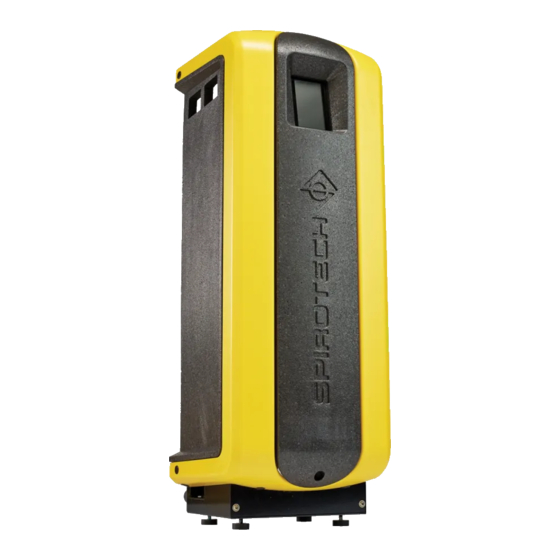
INTRODUCTION Overview of the unit S400-B S400 S400-R Outlet connection Check valve of the outlet Inlet connection Flow limiter outlet Pump Solenoid valve Power terminal Pressure sensor Control unit (HMI) Control unit - Power box Fuses Flow limiter inlet SmartSwitch Y-filter Automatic air vent Cover... - Page 4 Operation The figure below schematically shows the operation of the unit. The letter indications correspond with the main figure on the previous page. S400 S400-B S400-R...
- Page 5 Remote monitoring 2.2.1 General The Spirovent Superior is a fully automatic vacuum degasser for heating and cooling installations, filled with heat transfer fluids. These fluids contain dissolved and 2.4.1 Building Management System (BMS) free gases. The Spirovent Superior removes these gases The Superior has a series of external connectors for from the installation, preventing problems, caused by remote monitoring and control.
- Page 6 Type: Power input: Voltage / Frequency: IP class: Pressure PS: Temperature TS: Serial no.: Year of manufacture: Spirotech bv - The Netherlands Type of the unit Absorbed power Supply voltage Protection class System pressure System temperature Serial number Year of construction...
-
Page 7: Technical Specifications
TECHNICAL SPECIFICATIONS General specifications Item S400 S400-R S400-B Empty weight [kg] Noise level [dB (A)], at 1 m Fluid connections inlet/ Swivel G¾” female Swivel G¾” female Swivel G¾” female outlet Fluid connection refil Swivel G¾” female Swivel G¾” female Swivel G¾”... -
Page 8: Safety
SAFETY Unpack WARNING Safety instructions To prevent damage to the unit do not hoist Refer to the safety instructions document for the safety the unpacked unit. instructions and other safety information. The unit is delivered on a pallet. INSTALLATION AND COMMISSIONING Installation conditions Install the unit on a frost-free, well-ventilated place. - Page 9 Mounting and installation 5.3.1 Mounting Remove the fastener (A). Remove the cover (B) from the unit. Floor mounting: Place the unit on a flat surface, against a flat, closed wall. Mount the unit to the floor. Use brackets and adequate fasteners. Wall mounting: Mount the unit to a flat, closed wall using the holes and spacers.
- Page 10 Insert a valve (B) in each branch. Preferably, use (-R versions): Insert a shutoff valve (A) and a lockable ball valves. backflow protection (B) in the makeup water supply line. And then connect it to the flexible refill line (C). NOTE With these valves the unit can be isolated.
- Page 11 Loosen and remove the connector cap (A). Fasten the connector cap (B) to the connector (C). Put back the connector in the frame. Fasten the cable gland (A). Feed a 3-core supply cable (C) through cable gland (A) and the connector cap (B). Contact Connector External refill...
-
Page 12: Pump
For internet connection, either connect the LAN Open the deaeration valve (A) to deaerate the cable to the LAN connector (A), or connect the WiFi pump. dongle (optional) to the USB connector (B). CAUTION Make sure that the LAN cable does not touch warm parts. - Page 13 The Automatic Commissioning consists of several steps: Set the pressure levels Push the start button to start the commissioning procedure. Select the preferred language, refer to Select the preferred language. Set the actual time and date, refer to Set the actual time and date.
- Page 14 When the display shows that the test is completed 5.4.4 Finish the startup successfully, push the OK button and proceed to the next step, refer to § 5.4.4. The display shows the home screen and the status is standby. NOTE During the functional test, warnings and faults can be triggered (refer to §...
-
Page 15: Operation
OPERATION Button/indicator Description WiFi indicator HMI (user interface) description This section shows an overview of the content on the Error indicator display. 6.1.1 Screen layout Warning indicator Radio button (not selected) Radio button (selected) Action button (available) Degass start Degass start Action button (not available) Critical system fill Critical system fill... - Page 16 Page Content Main menu Main Menu Navigation buttons to go to other Page Content pages: Software upgrade Only accessible for Spirotech Network Shows the type of network Operating mode User settings Help Navigation buttons to go to help History pages:...
- Page 17 General settings Refill settings (only for S400-R and S400-B versions) Parameter Description Parameter Description System fluid System fluid. Refill volume Maximum allowed refill quantity alarm after per refill. Issues an alarm if a refill Select the used system fluid out of exceeds this threshold.
- Page 18 Switch on the unit CAUTION Manually started degassing will not be Connect the unit to the mains power. controlled by the Smart switch nor by Touch the display of the touchscreen. blocking times and will run continuously. NOTE Select the button Stop processes to stop the The start page shows on the display.
-
Page 19: Failures
FAILURES Taking out of operation WARNING Remedy failures Make sure that it is not possible to WARNING unintentionally supply power to the system. In case of a failure always warn the installer. Remove the power and pressure from the unit before starting repairs. Refer to §... - Page 20 Failure table NOTE The number indications correspond with the main figures In case the Superior continues to run only 10 in § 2.1 and § 2.2. An overview of the replacement parts minutes per event, please check if: has been included in § 8.2. The gas concentration is sufficient (low NOTE enough).
- Page 21 General - all types (S400, S400-R, S400-B) Problem Possible cause Correction The inlet valve is closed Open the valve. W31 / E31 The inlet line is (partly) blocked Remove the obstruction. Fill time too long The filter (24) is clogged Clean the filter element.
- Page 22 Only applicable to the systems with the refill functionality (S400-R, S400-B) Problem Possible cause Correction A leak in the system Repair the leak. Big installation Check the settings Refill volume Refill: too much alarm. The inlet valve is closed Open the valve. The inlet is blocked Check and clean the inlet.
-
Page 23: Maintenance
MAINTENANCE Replace the interior of the solenoid valve (22) every year. Always fix the vapor-tight insulation after Periodic maintenance maintenance. With every periodic inspection, check the float valve (31) by removing some water from the break tank NOTE (30), or by a short push on the float of the float valve (31). -
Page 24: Flow Limiter Refill
Main item Spare part Article number Outlet Check valve, including O-ring, outlet R61.417 Flow limiter R61.416 House limiter R73.224 Refill line Flow sensor R61.424 Flow limiter refill R61.443 Non-return valve R61.423 Solenoid valve - internal parts R12.003 Solenoid valve - coil R10.343 Level sensor Level sensor... - Page 25 Maintenance card Type: Serial number: Installation date: Installed by firm: Installed by technician: Inspection date: Technician: Initials: Nature of the maintenance: Inspection date: Technician: Initials: Nature of the maintenance: Inspection date: Technician: Initials: Nature of the maintenance: Inspection date: Technician: Initials: Nature of the maintenance: Inspection date:...
-
Page 26: Guarantee
GUARANTEE Terms of guarantee The guarantee for Spirotech products is valid until 2 years following the purchasing date. The guarantee lapses in cases of faulty installation, incompetent use and/or non-authorised personnel trying to make repairs. Consequential damage is not covered by the... -
Page 27: Ce Statement
The Netherlands Technically represented by the Manager PD&I, declares that the vacuum degassers: Spirotech SpiroVent Superior, models: S4, S400, S6, S600, S10 and S16 (all types) Are in compliance with all relevant demands of the following European Direc ves: Machine Direc ve - 2006/42/EC... - Page 28 © Copyright Spirotech bv...
Need help?
Do you have a question about the SPIROVENT SUPERIOR S400 and is the answer not in the manual?
Questions and answers