Table of Contents
Advertisement
Quick Links
1. AVR lab board
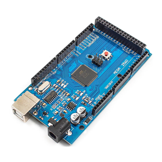
Figure 1 shows a picture of the assembled lab board that contains peripherals, connectors, and
the Arduino MEGA 2560 R3 microcontroller board. The serial number of my lab board is #168.
Wiring
2.
This wire connection worked on AVR lab borad #168.
AVR Pins (top and bottom row)
Port Group
PORT F
PORT F
PORT F
PORT F
PORT F
PORT F
PORT F
PORT F
PORT E
PORT D
PORT D
PORT A
PORT A
USER'S MANUAL
Figure 1: AVR Lab Board
Pin
PF0
PF1
PF2
PF3
PF4
PF5
PF6
PF7
PE2
RDX4
RDX3
PA4
PA5
Input/Output Device Pins (middle row)
Port Group
LCD DATA
LCD DATA
LCD DATA
LCD DATA
LCD DATA
LCD DATA
LCD DATA
LCD DATA
MOTOR
INPUTS
INPUTS
LCD CTRL
LCD CTRL
Pin
D0
D1
D2
D3
D4
D5
D6
D7
Mot
PB0
PB1
BE
RW
Advertisement
Table of Contents

Related Manuals for Arduino MEGA 2560 R3


Summary of Contents for Arduino MEGA 2560 R3
- Page 1 1. AVR lab board Figure 1 shows a picture of the assembled lab board that contains peripherals, connectors, and the Arduino MEGA 2560 R3 microcontroller board. The serial number of my lab board is #168. Figure 1: AVR Lab Board Wiring This wire connection worked on AVR lab borad #168.
- Page 2 PORT A LCD CTRL PORT A LCD CTRL PORT C KEYPAD PORT C KEYPAD PORT C KEYPAD PORT C KEYPAD PORT C KEYPAD PORT C KEYPAD PORT C KEYPAD PORT C KEYPAD PORT L LED BAR LED2 PORT L LED BAR LED3 PORT L LED BAR...
- Page 3 Figure 2: Initial State 4. Start Figure 3 shows a picture of the start state. After pressing PB0 to start the program, the LED lights is going to flash. When it flashes three times, then you can start to input the location of the accident.
- Page 4 Figure 4: Input State 6. Input Accident Location Figure 5 ~ Figure 7 show every step of inputting accident location, which has two parameters x and y. Figure 5: Input the x value...
- Page 5 Figure 5 shows what is on the LCD when the user input the x value of the accident location. Here we take 22 as an example. Figure 6: End of the x value After pressing ‘*’ key, there comes a comma on the LCD. This means the input of the first value x is finished, and the user can input next value y now.
- Page 6 Figure 7: Input the y value Figure 7 shows that LCD displays what you input for y value of the accident location. Then user can press ‘#’ to end the input of the y value, and it means user has already finished the input of the accident location.
- Page 7 Figure 9: Found the accident location 9. Fly Back Figure 10 shows what display on the board when the drone flies back. Figure 10: Drone flies back Abort State Figure 11 shows the Abort State. Every time user press PB1 to input ‘Abort’ state to the program,...
- Page 8 the LCD displays Figure 11. Figure 11: Abort State...
Need help?
Do you have a question about the MEGA 2560 R3 and is the answer not in the manual?
Questions and answers