Table of Contents
Advertisement
Quick Links
Advertisement
Table of Contents

Related Manuals for Bartell Global CONTEC MODUL 200


Summary of Contents for Bartell Global CONTEC MODUL 200
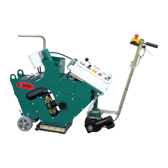
- Page 1 MODUL 200 ® Mobile Shotblaster Instruction manual...
-
Page 2: Table Of Contents
® Manual MODUL 200 - 2 - INDEX 1. Machine applications ...3 2. Technical data ...3 3. Safety rules ...3 4. Operating and blasting ...4 5. Maintenance and adjustments ...6 Adjusting the blast track ...6 Adjusting the height of the blaster ...7 Wear &... -
Page 3: Machine Applications
® Manual MODUL 200 - 3 - 1 Machine applications Shotblasting of horizontal, dry floors such as concrete and steel surfaces with or without a ® coating and asphalt using CONTEC blasting tools. The use of the machine outside is only possible in dry weather. -
Page 4: Operating And Blasting
® Manual MODUL 200 - 4 - Never wear loose or badly fitting clothing. Flapping sleeves may be pulled into the machine causing serious injury. All rotating parts of the machine are suitably protected by covers, which prevent clothes or similar from entering the machine. - Page 5 ® Manual MODUL 200 - 5 - ® phases, 230 V, 60 Hz connection. When operating a double unit (MODUL 200 + MODUL ® EU) a 63 A, 3 phases, 60 Hz connection is required. Check the floor for screws, nuts, or stones etc., and sweep the floor if necessary, with a brush ®...
-
Page 6: Maintenance And Adjustments
® Manual MODUL 200 - 6 - direction is indicated by a red arrow on the belt drive cover (Appendix diagram No. 187). In case of wrong rotation, switch the shotblaster off and disconnect the main cable. The plug of the machine is a phase reverse plug. -
Page 7: Adjusting The Height Of The Blaster
® Manual MODUL 200 - 7 - clockwise. Turn in a clockwise direction if the path is heavier on the right-hand side. Reconnect the shot enter pipe with the clamps, connect the shot hose and try a short test run. Repeat the adjustment if necessary, until the path is smooth, even and without variation. -
Page 8: Wear & Tear On The Linings
® Manual MODUL 200 - 8 - The shot cage (Appendix diagram No. 119) is like the blast wheel – a pure wear & tear part and must be checked regularly. Two different kinds of wear & tear on the cage are possible. The window in the cage has a width of 30 mm. -
Page 9: Wear & Tear On The Back Skirt
® Manual MODUL 200 - 9 - of the motor flange (Appendix diagram No. 181) is a nut. Turn this in a clockwise direction until the tension of the belt is correct. Tighten the four screws of the motor and tighten the nut. -
Page 10: Troubleshooting
® Manual MODUL 200 - 10 - 6 Troubleshooting If, after activating the machine by pressing “START” the run lamp is lit but all or part of the motor is not running – check the following: - Is the power connection correct? - Are the cables in a good condition and properly laid? - Are the fuses in the control panel closed? - Is the motor overload protection in the control panel closed? -
Page 11: The Modular System
® Manual MODUL 200 - 11 - 7 The modular system ® ® Connecting MODUL 200 EU to MODUL 200 ® ® In the following the connection of a MODUL 200 EU to a MODUL 200 basic unit is described. It is assumed, that the control panel for a double unit has already been prepared. -
Page 12: Wear & Tear Parts
® Manual MODUL 200 - 12 - 8 Wear & tear parts Definition of wear & tear parts: Blast wheel, Shot cage, Linings, Magnetic frame, Bracket for the back skirt, Back skirt, Rubber sealing for the magnetic frame, Shot stop, Blast wheel cover, Shot hose, Poly-V belt of the turbine, Poly-V Pulleys of the turbine... - Page 13 ® Manual MODUL 200 - 13 - PARTS BREAKDOWN ® CONTEC Maschinenbau & Entwicklungstechnik GmbH © CONTEC 2016 Hauptstrasse 146, 57518 Alsdorf (Sieg) / Germany Tel: +49 (0) 2741 9344-0 Fax: +49 (0) 2741 9344-29...
- Page 14 ® Manual MODUL 200 - 14 - ® CONTEC Maschinenbau & Entwicklungstechnik GmbH © CONTEC 2016 Hauptstrasse 146, 57518 Alsdorf (Sieg) / Germany Tel: +49 (0) 2741 9344-0 Fax: +49 (0) 2741 9344-29...
- Page 15 ® Manual MODUL 200 - 15 - Item # Part # Description 8750203308 Contact Element 8750202309 Mounting Adapter 8750101000 Complete Control Panel 8755140075 Motor 7,5 KW 8710100000 Machine Frame 8730102700 Shot Compartment Cover left and right 8730100104 Bar for Control Panel Bracket 8730100103 Bracket Control Lever 8730100400...
- Page 16 ® Manual MODUL 200 - 16 - ® CONTEC Maschinenbau & Entwicklungstechnik GmbH © CONTEC 2016 Hauptstrasse 146, 57518 Alsdorf (Sieg) / Germany Tel: +49 (0) 2741 9344-0 Fax: +49 (0) 2741 9344-29...
- Page 17 ® Manual MODUL 200 - 17 - Item # Part # Description 8720120008 Side Lining Blast Chamber 8720120005 Top Lining Blast Chamber 8720120003 Lining Blast Chamber Bearing Housing 8720120004 Front Lining Blast Chamber Blast Wheel Cover 8720120007 Side Lining Reclaim Chamber 8720120002 Lining Reclaim Chamber inside 8720120001...
- Page 18 ® Manual MODUL 200 - 18 - ® CONTEC Maschinenbau & Entwicklungstechnik GmbH © CONTEC 2016 Hauptstrasse 146, 57518 Alsdorf (Sieg) / Germany Tel: +49 (0) 2741 9344-0 Fax: +49 (0) 2741 9344-29...
- Page 19 ® Manual MODUL 200 - 19 - Item # Part # Description 8730101100 Side Covering right 8730101000 Side Covering left 8770270070 Cap 70 mm 8770271070 Plug for hole diameter 70 mm 8730101400 Right magnetic Frame 8730101300 Left magnetic Frame 8770238006 Rubber Sealing magnetic Frame 8730102401 Side Bracket for Rubber...
- Page 20 ® Manual MODUL 200 - 20 - ® CONTEC Maschinenbau & Entwicklungstechnik GmbH © CONTEC 2016 Hauptstrasse 146, 57518 Alsdorf (Sieg) / Germany Tel: +49 (0) 2741 9344-0 Fax: +49 (0) 2741 9344-29...
- Page 21 ® Manual MODUL 200 - 21 - Item # Part # Description 875020304A Fuse 4 A slow 8750203015WEG Drive Circuit 8750202018 Potentiometer 8750202011 Speed Scale 8750202010 Potentiometer Speed Button only 8751203025 Ampmeter 8751203000 Cover for Ampmeter 8751202004 Star-Delta Switch 8750202303 Direction Switch 8750202302N Start Button...
- Page 22 ® Manual MODUL 200 - 22 - ® CONTEC Maschinenbau & Entwicklungstechnik GmbH © CONTEC 2016 Hauptstrasse 146, 57518 Alsdorf (Sieg) / Germany Tel: +49 (0) 2741 9344-0 Fax: +49 (0) 2741 9344-29...
- Page 23 ® Manual MODUL 200 - 23 - ® CONTEC Maschinenbau & Entwicklungstechnik GmbH © CONTEC 2016 Hauptstrasse 146, 57518 Alsdorf (Sieg) / Germany Tel: +49 (0) 2741 9344-0 Fax: +49 (0) 2741 9344-29...
Need help?
Do you have a question about the CONTEC MODUL 200 and is the answer not in the manual?
Questions and answers