Table of Contents
Advertisement
Quick Links
Advertisement
Table of Contents

Related Manuals for Ursalink EM500-SWL Series

Summary of Contents for Ursalink EM500-SWL Series
-
Page 2: Table Of Contents
EM500-SWL Payload Structure V1.0 Contents 1. Uplink Payload Structure......................2 Uplink Packet Example......................2 2. Downlink Payload Structure....................3 Downlink Packet Example....................3 3. Data Types..........................4 3.1 IPSO Standard Definition....................4 3.2 Ursalink Custom Format....................4 3.3 LoRaWAN Parameter.....................5... -
Page 3: Uplink Payload Structure
Frame N+1: Battery level changes uplink. 01 75 64 Channel Type Value 64 =100 means 100% (Battery) (Battery Level) Frame N+2: Content will be reported each time when device reboots: Ursalink Custom Format Version + SN + Hardware Version + Software Version + Class Type... -
Page 4: Downlink Payload Structure
ff 0b ff ff 01 01 Channel Type Value Channel Type Value 0b = 11 01 = 1 01 = 1 ff=255 (Device Restart ff=255 (Custom Format (reserved) (Version 1) Notification) Version) ff 16 61 26 a1 08 75 05 00 35 Channel Type Value... -
Page 5: Data Types
Frame N+1 03 77 6b 00 Channel Type Value 77 means water level 6b 00 => 00 6b = 107 means 107 cm 3.2 Ursalink Custom Format Type Type ID Data Size Data Resolution (per bit) Ursalink Custom Format 0x01... -
Page 6: Lorawan Parameter
Software Version 0110 => 0x01 0x10 Device Restart Notification 0xff reserved Device Power Off 0xff reserved Notification Class Type 00: Class A 6410908243750001 => Device SN (8 Bytes) 0x6410908243750001 3.3 LoRaWAN Parameter DevEUI 24E124 + 2 to 11 digits of SN e.g. - Page 7 Please clarify your application environment before deployment so that the device can function well. The device is not intended to be used as a reference sensor, and Ursalink will not should responsibility for any damage which may result from inaccurate readings.
- Page 8 7.1.2 Basic Settings-ABP....................20 7.1.3 Channel Settings.......................22 7.2 Device Settings........................23 7.2.1 General........................23 7.2.2 Data Calibration......................24 7.2.3 Threshold........................24 8.Sensor Management via Ursalink Cloud..................25 8.1 Ursalink Cloud Registration....................25 8.2 Add a Ursalink LoRaWAN Gateway..................25 8.3 Add EM500-SWL to Cloud....................26...
-
Page 9: Overview
Sensor data are transmitted in real-time using standard LoRaWAN protocol. LoRaWAN enables encrypted radio transmissions over long distance while consuming very little power. The user can obtain sensor data and view the trend of data change through Ursalink Cloud or thr ough the user's own Network Server. -
Page 10: Dimensions(Mm)
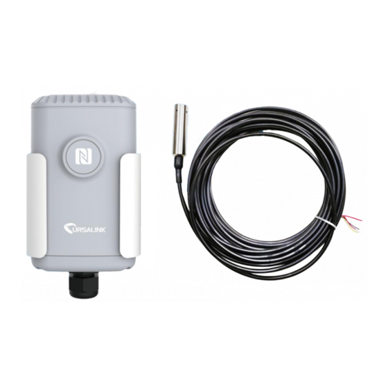
2 × Mounting 1 × Hose 1 × Warranty 1 × Quick Guide Screws Clamp Card (Include cable and transmitter) 1 × DIN Rail (Optional) If any of the above items is missing or damaged, please contact your Ursalink sales representative. -
Page 11: Product Overview
EM500-SWL User Guide 2.2 Product Overview Front View: ①LoRa Antenna (Internal) ②NFC Area ③Water-proof Connector Back View: ④Battery (Internal) ⑤Wall Mounting Holes ⑥Pole Mounting Holes 3. Sensor Connection with EM500 Follow below to connect transmitter cable to EM500 device if they are separated. 1. -
Page 12: Sensor Installation
EM500-SWL User Guide 3. Pull out the motherboard, insert and lock 4. Put the motherboard back and restore the wires accordingly (see the label on the everything in its due position. motherboard or following picture). Pinouts: Color Description White Yellow Black VOUT=12V Sensor Installation... -
Page 13: Em500 Installation
EM500-SWL User Guide If the transmitter is to be used in a well or other locations with turbulence or other disturbances, it is advisable to install a pipe to protect the transmitter. Several holes should be drilled at different heights of the pipe in order to let water flow into and remove dydrodynamic pressure. Note: The pipe can’t be placed bend. -
Page 14: Din Rail Mounting
DIN rail on the mounting bracket. It is necessary to choose a standard bracket. 5.Turn ON/OFF the Sensor EM500-SWL series can be turned ON/OFF via smartphone or computer with NFC (Near Field Communication) or button. Select one of following methods to turn on/off the device. - Page 15 EM500-SWL User Guide 4. Device information will be shown on the APP. 5. Switch the button of Device Status to turn on or off the device. 6. Enter the correct password (Default password: 123456) and wait a few seconds until APP shows “Operate Successful!”.
-
Page 16: Turn On/Off Via Pc Software
EM500-SWL User Guide 5.2 Turn ON/OFF via PC Software 1. Download Ursalink configuration software “Toolbox” and open the software. 2. Connect NFC reader to computer and attach the device to NFC reader. 3. Select type as NFC and serial port of NFC reader, then click “save”. -
Page 17: Turn On/Off Via Button
Press the button until LED blinks rapidly to reset the device to factory default. (Over 10 seconds) 6.Sensor configuration Ursalink EM500-SWL series sensors can be monitored and configured via NFC technology. In order to protect the security of sensor, password validation is required when turning on/off the sensor or changing configuration. -
Page 18: Read Configuration
EM500-SWL User Guide 6.1.1 Read Configuration 1. Open APP “Toolbox” and click “Read” to read current information of device. 2.Attach the smartphone with NFC area to the device until the APP shows “Read Successful!”. Note: Failing to read can be caused by long distance, wrong location, or rapid movement. 6.1.2 Write Configuration 1. -
Page 19: Template Settings
EM500-SWL User Guide 3. Enter password (default password: 123456). 4. Attach the smartphone with NFC area to the device and wait a few seconds until APP shows “Write Successful!”. The device will automatically re-join the network if LoRaWAN paramters are changed. - Page 20 EM500-SWL User Guide 2. Attach the smartphone with NFC area to another device. 3. Select the template file from Toolbox APP and click “Write”. 4. Enter password of this device and keep the two devices close until the APP shows “Write successful!”.
-
Page 21: Configuration Via Pc
EM500-SWL User Guide 6.2 Configuration via PC Make sure “Toolbox” is downloaded on your computer. 6.2.1 Read Configuration 1. Open software “Toolbox” and click “Read” to read current information of device. 3. Attach the device to the NFC reader until Toolbox shows “success”. Note: Failing to read can be caused by long distance, wrong location, or rapid movement. -
Page 22: Upgrade
EM500-SWL User Guide 3.Press Enter key to write and attach the device close to NFC reader until “Write” button disappear. The device will automatically re-join the network if LoRaWAN paramters are changed. Note: Keep the two devices close and don’t move them in order that you can get the best connectivity as possible when writing data via NFC. -
Page 23: Template And Reset
EM500-SWL User Guide 6.2.3.2 FOTA 1. Make sure your computer can access the Internet. 2. Click “Check for Updates” to search for the latest firmware via computer Internet and upgrade. Note: Keep the two devices close and don’t move them in order that you can get the best connectivity as possible when upgrading. -
Page 24: Sensor Parameters (For App And Pc)
7.Sensor Parameters (for App and PC) 7.1 LoRa WAN Settings 7.1.1 Basic Settings-OTAA Location: Ursalink ToolBox(PC): LoRaWAN Settings → Basic Ursalink ToolBox(APP): Device → Settings → LoRaWAN Settings Basic Settings-OTAA Item Description Default Enter the application EUI.The Network Server receives... -
Page 25: Basic Settings-Abp
MAC command. Enabled Disabled: Whatever how the signal quality is, the Network Server will not adjust the datarate of the device. 7.1.2 Basic Settings-ABP Location: Ursalink ToolBox(PC): LoRaWAN Settings → Basic Ursalink ToolBox(APP): Device → Settings → LoRaWAN Setting... - Page 26 EM500-SWL User Guide Basic Settings-ABP Item Description Default Enter the application EUI.The Network Server receives request and consults the entity associated with the 24e124c0002 App EUI APP EUI to validate the request.If permission is a0001 granted, it responds with a join-accept message. Select from: "OTAA"...
-
Page 27: Channel Settings
Location: Ursalink ToolBox(PC): LoRaWAN Settings → Channel Ursalink ToolBox(APP): Device → Settings → LoRaWAN Settings Note: Make sure the LoRa channel configuration of EM500-SWL matches the LoRaWAN gateway. LoRa frequency configuration is as follows if the sensor LoRa frequency is one of... -
Page 28: Device Settings
16 channels numbered 80 to 95 utilize LoRa 125 kHz BW starting at 486.3 MHz and incrementing linearly by 1.6 MHz to 489.3. 7.2 Device Settings 7.2.1 General Location: Ursalink ToolBox(PC): Device Settings → General Ursalink ToolBox(APP): Device → Settings → General Settings Device General Settings Item Description Default Device Type Show the type of the device. -
Page 29: Data Calibration
EM500-SWL User Guide 7.2.2 Data Calibration Location: Ursalink ToolBox(PC): Device Settings → Data Calibration Settings Ursalink ToolBox(APP): Device → Settings → Data Calibration Settings Note: It is recommended to do the calibration before using the device. Data Calibration Settings Item... -
Page 30: Sensor Management Via Ursalink Cloud
8.1 Ursalink Cloud Registration Register and log in Ursalink Cloud. Ursalink Cloud URL: https://cloud.ursalink.com/login.html 8.2 Add a Ursalink LoRaWAN Gateway 1. Enable “Ursalink” type network server and “Ursalink Cloud” mode in gateway web GUI. Note: Ensure gateway has accessed the Internet. -
Page 31: Add Em500-Swl To Cloud
EM500-SWL User Guide 2.Go to “My Devices->Gateway” of Ursalink Cloud and click “Add” to add gateway to Ursalink Cloud via SN. 3.Check if gateway is online in Ursalink Cloud. 8.3 Add EM500-SWL to Cloud 1. Go to “Device->My Devices” and click “Add Device”. Fill in the SN of EM500-SWL and select... - Page 32 EM500-SWL User Guide 2.After EM500-SWL is connected to Ursalink Cloud, Click or “History Data” to check the data on Ursalink cloud. -END-...
Need help?
Do you have a question about the EM500-SWL Series and is the answer not in the manual?
Questions and answers