Table of Contents
Advertisement
Quick Links
Advertisement
Table of Contents

Related Manuals for urmet domus IPerCom-2Voice


Summary of Contents for urmet domus IPerCom-2Voice
- Page 1 IPerCom-2Voice hardware installation guide www.urmet.co.uk technical@urmet.co.uk...
-
Page 3: Table Of Contents
Contents IPerCom-2Voice system schematic Page 1 IPerCom-2Voice combined with iPassan access control system schematic Page 2 Network installation and configuration requirements Page 3 & 4 2Voice riser installation Page 4 & 5 System connections Page 6 & 7 DIP switch settings Page 8 &... - Page 4 Contents continued 1060/13 Elekta, 1060/18 & 1060/19 Elekta Steel Call Modules Connections overview Page 23 Maglock connection example Page 24 Fail safe and fail secure release connection examples Page 25 Interface to iPassan and third party access control systems Page 26 1060/18 &...
-
Page 5: Ipercom-2Voice System Schematic
IPerCom-2Voice schematic This schematic shows the IPerCom video entry system with integrated U R MET U R MET IPerCom proximity 1083/55 access control Maximum distance from U R MET U R MET Cat5e 1083/20..1083/59 to the furthest monitor or handset is 125M... -
Page 6: Ipercom-2Voice Combined With Ipassan Access Control System Schematic
IPerCom-2Voice with iPassan schematic This schematic shows the IPerCom video entry U R MET U R MET system with iPassan 1083/55 proximity access control Maximum distance from U R MET U R MET Cat5e 1083/20..1083/59 to the furthest monitor or... -
Page 7: Network Installation And Configuration Requirements
Network installation and configuration requirements The installation should be installed, tested and documented as per the following standards – European Committee for Electrotechnical Standardisation (CENELEC) EN 50173 Information Technology – Generic Cabling Systems EN 50173-1:2011 General requirements EN 50173-2:2007 + A1:2010 Office Premises EN 50173-3:2007 + A1:2010 Industrial Premises... -
Page 8: 2Voice Riser Installation
Specific network requirements for IPerCom are as follows – IGMPv2 or IGMPv3 Multicast Service must be enabled. The following ports must be open and not restricted – TCP ports 2049, 51234, 5060, 50118, 3306, 13451 to 3460, 111, 80, 433, 41365, 22, 918 &... - Page 9 U R MET U R MET U R MET U R MET Cat5e This method is used where there are more than 50 monitors in a building. U R MET U R MET Any number of 1083/59 Gateways and Cat5e 1083/20 Power Supplies can be used to increase the number of monitors in a Cat5e...
-
Page 10: System Connections
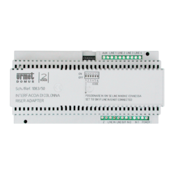
System connections To LINE IN of the 1083/55 Distributor 2Voice system connections are non-polarised 1083/59 GAT EWAY IPERCOM STATUS LED PROGR./ RESET 2VOICE STATUS LED POWER LINE 1 LINE 2 IN 0 IN 1 CARD IP network LINE 1 LINE 2 CAUTION 1083/20A Sch./Ref. - Page 11 System connections continued Important note – At the same time as connecting the monitor or handset, you must set the DIP switches and make a note of the apartment number (postal address) on the commissioning sheets provided. LIN E1 LIN E2 LIN E3 LIN E4 Sch.
-
Page 12: Dip Switch Settings
Monitor and handset DIP switches Regardless of the apartment postal addresses, the DIP switches must start at USER 0 (binary address 0), and increase consecutively as shown below – U R MET U R MET U R MET U R MET U R MET U R MET U R MET... - Page 13 Monitor and handset DIP switches In systems where the riser or block is split into sections using more than one 1083/59 Gateway, the monitor or handset DIP switches for each section must start at USER 0 (binary address 0) – U R MET U R MET U R MET...
-
Page 14: 2Voice Riser Connection And Installation Rules
2Voice riser connection rules To create a second riser, you CANNOT connect 1083/55 Distributors in this way – L IN E1 LIN E2 LIN E3 L IN E4 Sch. 1083/55 LIN E IN L IN E OU T L IN E1 L IN E2 LIN E3 LIN E4... - Page 15 2Voice riser connection rules continued Do not ‘double up’ any 2Voice connections – LINE U R MET Keep the conductor pairs twisted as close to the terminals as possible – LINE U R MET LINE Do not leave cables terminated at one end and un-terminated at the other – U R MET U R MET U R MET...
-
Page 16: 2Voice Fault Finding
2Voice riser fault finding If the fault is limited to one monitor or handset – Assuming that the configuration and DIP switches have been checked first and are correct, the issue is either the 1083/55 Distributor, the cable between the 1083/55 and the monitor/handset, or the monitor/handset itself. - Page 17 If the fault is affecting the whole riser – Assuming that the configuration and DIP switches have been checked first and are correct – Disconnect LINE 1 (and LINE 2 if connected) of the 1083/59 Gateway. Connect a monitor or handset using a new short piece of cable directly to LINE 1 of the 1083/59.
-
Page 18: 1750/1 Miro Video Monitor
1750/1 Miro video monitor Controls and functions –... -
Page 19: Installation
Installation – Connections – Apartment Urmet 1072/59 doorbell button Extension Sounder S- S+ To the 2Voice system (1083/55 LINE1 - LINE 4) -
Page 20: 1750/5 Or 1750/6 Miro Hands-Free Video Monitor
1750/5 (Black) & 1750/6 (white) Miro hands-free video monitor Controls and functions –... -
Page 21: Installation
Installation –... -
Page 22: Connections
Connections – Urmet 1072/59 Panic input device Extension Sounder (normally open contact) Apartment doorbell button S+ S- Connections to Yokis lighting control (where fitted) -
Page 23: 1183/5 Miro Audio Handset
1183/5 Audio handset Controls and functions – Installation –... -
Page 24: Connections
Connections – Apartment Urmet 1072/59 doorbell button Extension Sounder S- S+ To the 2Voice system (1083/55 LINE1 - LINE 4) -
Page 25: 1183/7 Miro Hands-Free Audio Station
1183/7 Hands-free audio station Controls and functions –... -
Page 26: Installation
Installation – Connections – LINE IN GT Y1 To the 2Voice system (1083/55 LINE1 - LINE 4) Apartment doorbell button Urmet 1072/59 Extension Sounder... -
Page 27: Connections Overview
1060/13 Elekta, 1060/18 & 1060/19 Elekta Steel Call Modules Connections for 1060/13 Elekta and 1060/18 & 1060/19 Elekta Steel entry panels are identical - NC NO SE+ SE- LAN – Network connection to PoE network switch port AD - Input for hearing aid induction loop SE2 - Normally open voltage free relay output specifically for triggering vehicle automation systems. -
Page 28: Maglock Connection Example
Typical connections for a maglock – Lock power supply NC NO SE+ SE- Fit a varistor as close as possible to the maglock connections. Failure to fit this component can damage the entry panel and automatically invalidates the warranty. Varistor Maglock N.C. -
Page 29: Fail Safe And Fail Secure Release Connection Examples
Typical connections for fail safe (fail open) electric release - Lock power supply NC NO SE+ SE- Varistor Fit a varistor as close as possible to the electric release connections. Failure to fit this component can damage the entry panel and automatically invalidates the warranty. -
Page 30: Interface To Ipassan And Third Party Access Control Systems
Interfacing IPerCom lock output to iPassan access control system - SE+ SE- V V NC NO 1104/921 iPassan controller or 1104/926 iPassan 2-Reader expansion card The IPerCom volt free relay lock output is connected to the exit switch input of the iPassan controller. The IPerCom relay time should be programmed to 1 second and the actual door open time required is programmed via the iPassan (or third party) access control system. -
Page 31: 1060/18 & 1060/19 Mounting Height
1060/18 & 1060/19 mounting height BS8300 6.6 for access control systems refers to the activation pad height of between 900mm and 1050mm. The “Activation Pad” i.e. the proximity reader is centred at a height of 1035mm. Wheelchair Housing Design Guide (WHDG) refers to a height of 1200mm to the highest function. -
Page 32: 1060/13 Mounting Height
1060/13 mounting height BS8300 6.6 for access control systems refers to the activation pad height of between 900mm and 1050mm. The “Activation Pad” i.e. the proximity reader is centred at a height of 1050mm. Wheelchair Housing Design Guide (WHDG) refers to a height of 1200mm to the highest function. -
Page 33: 1060/74 Sinthesi Steel Entry Panel
1060/74 Sinthesi Steel entry panel module AD/ILA TLC-EXT IC2 DIGITAL CONNECTOR LAN – Network connection to PoE network switch port SE+ SE- Output for direct connection to a fail secure (fail locked) release. SE2 - C NC NO - Voltage free relay output specifically for triggering vehicle automation systems. This output is triggered by the button with one ‘dot’... -
Page 34: Maglock Connection Example
Typical connections for a maglock – Lock Pt No power 788/100 supply The 788/100 is a miniature relay designed to fit inside the 1060/74 back box Maglock AD/ILA Varistor Fit a varistor as close as possible to the maglock connections. Failure to fit this component can damage the entry panel and automatically invalidates the warranty. -
Page 35: Fail Safe And Fail Secure Release Connection Examples
Typical connections for fail safe (fail open) electric release - Lock Pt No 788/100 power supply The 788/100 is a miniature relay designed to fit inside the 1060/74 back box AD/ILA Varistor Typical connections for fail secure (fail locked) electric release - AD/ILA Varistor... -
Page 36: Interface To Ipassan And Third Party Access Control Systems
Interfacing IPerCom lock output to iPassan access control system – 1104/921 iPassan controller or 1104/926 iPassan 2-Reader expansion card The IPerCom lock output is connected to the 788/100 relay which triggers the exit switch input of the iPassan controller. The IPerCom lock time should be programmed to 1 second and the actual door open time required is programmed via the iPassan (or third party) access control system. -
Page 37: Mounting Height
1060/74 mounting height Wheelchair Housing Design Guide (WHDG) refers to a height of 1200mm to the highest function. Following the recommended mounting height the highest activation button is located at 1200mm. 2000 mm 2000 mm This places the top of the panel at 1365mm 1500 mm 1500 mm 87 degrees... -
Page 38: 1060/82 Proximity Key Reader
1060/82 proximity key reader module NO NC SP PA NO NC C – Voltage free clean contact lock release output rated at 30V @ 3.5A V+ V- Input for a local power supply, for use when PoE is not available. 44 – 57V DC @ 200mA LAN –... -
Page 39: Maglock Connection Example
Typical connections for a maglock – Maglock Lock power supply Varistor N.C. EMERGENCY DOOR RELEASE N.O. N.C. PRESS TO EXIT N.O. NO NC SP PA... -
Page 40: Fail Safe And Fail Secure Release Connection Examples
Typical connections for fail safe (fail open) electric release - Lock power supply Varistor NO NC SP PA Typical connections for fail secure (fail locked) electric release - Lock power supply Varistor NO NC SP PA... -
Page 41: Mounting Height
1060/82 mounting height BS8300 6.6 for access control systems refers to the activation pad height of between 900mm and 1050mm The “Activation Pad” i.e. the proximity reader is centred at a height of 1050mm. Wheelchair Housing Design Guide (WHDG) refers to a height of 1200mm to the highest function. -
Page 42: 1060/84 Relay Module
1060/84 Relay Module V+ V- PB1 – External normally open clean contact input 1 PB2 – External normally open clean contact input 2 OUT1 – NO NC C - Voltage free clean contact relay output rated at 30V DC @ 5.0A or 250V AC @ 5.0A OUT2 –... -
Page 43: 1060/41 Switchboard Handset
1060/41 Concierge Handset Plug the loudspeaker connector (green connector) into the PC loudspeaker output Plug the microphone connector (pink connector) into the PC microphone output Plug the USB connector into a spare USB port on the PC Internal connection – S+ S- Connection for 1072/59 External Sounder It is not necessary to install driver software for the 1060/41 Switchboard Handset. -
Page 44: Dip Switch Settings
Monitor/handset DIP switch settings... - Page 45 Monitor/handset DIP switch settings continued...
-
Page 46: Notes
Notes …………………………………………………………………………………………………………………………………………………………… …………………………………………………………………………………………………………………………………………………………… …………………………………………………………………………………………………………………………………………………………… …………………………………………………………………………………………………………………………………………………………… …………………………………………………………………………………………………………………………………………………………… …………………………………………………………………………………………………………………………………………………………… …………………………………………………………………………………………………………………………………………………………… …………………………………………………………………………………………………………………………………………………………… …………………………………………………………………………………………………………………………………………………………… …………………………………………………………………………………………………………………………………………………………… …………………………………………………………………………………………………………………………………………………………… …………………………………………………………………………………………………………………………………………………………… …………………………………………………………………………………………………………………………………………………………… …………………………………………………………………………………………………………………………………………………………… …………………………………………………………………………………………………………………………………………………………… …………………………………………………………………………………………………………………………………………………………… …………………………………………………………………………………………………………………………………………………………… …………………………………………………………………………………………………………………………………………………………… …………………………………………………………………………………………………………………………………………………………… …………………………………………………………………………………………………………………………………………………………… …………………………………………………………………………………………………………………………………………………………… …………………………………………………………………………………………………………………………………………………………… …………………………………………………………………………………………………………………………………………………………… …………………………………………………………………………………………………………………………………………………………… ……………………………………………………………………………………………………………………………………………………………... - Page 48 URMET COMMUNICATION AND SECURITY UK LTD Urban Hive, Skyline 120, Avenue West, Great Notley, Essex. CM77 7AA Tel 01376 556010 Fax 01376 567864 www.urmet.co.uk technical@urmet.co.uk...
Need help?
Do you have a question about the IPerCom-2Voice and is the answer not in the manual?
Questions and answers