Table of Contents
Advertisement
Quick Links
INSTALLATION GUIDE
May 2020 | 3725-86415-002A
Poly Medialign
GETTING HELP
For more information about installing, configuring, and
administering Poly/Polycom products or services, go to Polycom
Support.
Plantronics, Inc. (Poly – formerly Plantronics and Polycom)
345 Encinal Street
Santa Cruz, California
95060
© 2020 Plantronics, Inc. All rights reserved. Poly, the propeller
design, and the Poly logo are trademarks of Plantronics, Inc. All
other trademarks are the property of their respective owners.
Advertisement
Chapters
Table of Contents

Summary of Contents for Plantronics Poly Medialign 65
- Page 1 Plantronics, Inc. (Poly – formerly Plantronics and Polycom) 345 Encinal Street Santa Cruz, California 95060 © 2020 Plantronics, Inc. All rights reserved. Poly, the propeller design, and the Poly logo are trademarks of Plantronics, Inc. All other trademarks are the property of their respective owners.
-
Page 2: Table Of Contents
Set Up the Poly Medialign 65 System ........ -
Page 3: Before You Begin
65”, 75”, and 86” displays. ● Poly Medialign 65, with single 65” display ● Poly Medialign 75, with single 75” display ● Poly Medialign 86, with single 86” display ●... - Page 4 Before You Begin ● The Polycom Document Library provides support documentation for active products, services, and solutions. The documentation displays in responsive HTML5 format so that you can easily access and view installation, configuration, or administration content from any online device ●...
-
Page 5: Installation Overview
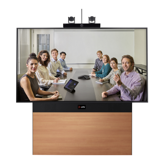
Installation Overview This chapter introduces the Poly Medialign (Model P019) system and provides the following information you need before you begin the physical installation of the Medialign system in the room. ● Installation Toolkit ● Installation Sequence Overview ● Pre-Installation Tasks Single Display Medialign Systems The Medialign single system contains a single frame that supports all configurations, panels with four different color options, and single 65”, 75”, or 86”... - Page 6 Installation Overview Poly Medialign 65 system, with single 65” display Poly, Inc.
-
Page 7: Dual Display Medialign Systems
Installation Overview Dual Display Medialign Systems The Medialign dual-display system contains dual 65”, 75”, or 86” displays. Poly Medialign 65D system, with dual 65” displays Poly, Inc. -
Page 8: Installation Toolkit
Installation Overview Installation Toolkit Most of the items you need to install the Medialign system are shipped with the system. However, you should also have the following items available before you begin the installation. Tools Needed for Installation ● Drill/driver ●... -
Page 9: Pre-Installation Tasks
Installation Overview 2 Attach speaker bracket assembly to the frame 3 Connect speaker cables 4 Secure the speaker bracket to the frame Install Components: 1 Install the PDU 2 Install the RealPresence Group Series 500 or G7500 codec Displays: 1 Attach display brackets to display 2 Mount the display to the base frame EagleEye Director II: 1 Attach EagleEye Director II base to camera bracket... - Page 10 Installation Overview Before beginning the physical installation, you must do the following: 1 Inspect the site. a Locate the equipment boxes and the room in which you plan to install the Medialign system. Ensure that the electrical box is accessible to disconnect power after installation of the system. If the electrical box is not accessible, a clearly-labeled POWER DISCONNECT switch must be installed in the room.
-
Page 11: Setting Up The Poly Medialign Single Display System
65”, 75”, or 86” display. Set Up the Poly Medialign Single Display Frame Set Up the Poly Medialign 65 System Set Up the Poly Medialign 75 System Set Up the Poly Medialign 86 System Set Up the Poly Medialign Single Display Frame This section describes how to set up the Poly Medialign single display frame used with either a 65”, 75”, or... - Page 12 Setting Up the Poly Medialign Single Display System Speakers 2565-84879-001 Wall Mount Bracket 1342-85958-001 12-24 × 1.25 Self-tapping Hex Screw 1601-52879-001 Power Distribution Unit (PDU) 1583-52876-008 M4 × 8 Screw 1601-42846-001 Codec Mount Bracket 1342-85957-001 RealPresence Group Series 500 Codec 2215-67205-001 G7500 Codec 2215-85256-001...
- Page 13 Setting Up the Poly Medialign Single Display System To install the Medialign single display frame: 1 Install power, network, and any other connectivity outlets in the areas shown in the following diagram. Medialign Single System Connections Area Center Line 306.75 mm 306.75 mm (12 1/16”) (12 1/16”)
- Page 14 Setting Up the Poly Medialign Single Display System For standard height, attach the horizontal support rail 1081.10 mm (42.56 in.) from the floor using eight wall anchors appropriate for your wall type (not supplied). Use the upper and lower holes in the rail.
- Page 15 Setting Up the Poly Medialign Single Display System If you want to mount the Medialign system higher than the standard height, you can add a 6” or 12” riser. With a 6” riser, attach the horizontal support rail 1219.48 mm (48.01 in.) from the floor using eight wall anchors.
- Page 16 Setting Up the Poly Medialign Single Display System With a 12” riser (Medialign 65 and Medialign 75 systems only), attach the horizontal support rail 1371.88 mm (54.01 in.) from the floor using eight wall anchors. WALL CENTER LINE OF UNIT 698.50mm 27.50in HORIZONTAL...
- Page 17 Setting Up the Poly Medialign Single Display System 3 Assemble the base frame on the floor. a Place two V-rails on the floor with the feet toward the wall where you plan to anchor the frame. Space them approximately 1350 mm (53 in.) apart. Orient the rails face down (open side up). Open Side Open Side 1350 mm...
- Page 18 Setting Up the Poly Medialign Single Display System c If using a riser kit, remove the leveling feet from the V-rails and install them in the risers. Screw them in to the risers until the lower edges of the feet extend 34 mm (1 5/16 in.) beyond the end of the riser.
- Page 19 Setting Up the Poly Medialign Single Display System d Place two horizontal frames between the V-rails. Orient them so that the faces with screw holes are toward the floor and the vertical straps are up. One rail edge of each frame has small screw holes and the other has large screw holes (circled in red in the next figure).
- Page 20 Setting Up the Poly Medialign Single Display System Attach two wall mount brackets to the lower rail of the upper horizontal frame using two M6 × 12 mm screws per bracket. (2) WALL MOUNT BRACKET 1342-85958-001 (4) M6 × 12 mm SCREW 1601-68586-001 g Center the frame assembly on the horizontal support rail.
- Page 21 Setting Up the Poly Medialign Single Display System h Attach the frame assembly to the horizontal support rail by driving two self-tapping screws through each wall mount bracket. Double check for plumb and level. CENTER LINE OF UNIT WALL (4) 12-24 X 1.25 mm SELF TAP HEX SCREW 1601-52879-001 WALL MOUNT BRACKET...
- Page 22 Setting Up the Poly Medialign Single Display System Attach the speakers to the speaker mount bracket using the M6 × 12 mm Phillips head screws supplied with the speakers. Orient the speakers so that the tweeters are toward the outside of the frame.
- Page 23 Setting Up the Poly Medialign Single Display System k Slide the lower slots of the speakers and bracket assembly over the screws and swing the assembly in place. Attach the RCA cables to the speakers. Route the connectors behind the speaker bracket and through the opening in the bracket.
- Page 24 Setting Up the Poly Medialign Single Display System m Secure the speaker / bracket assembly to the V-rails by installing two more M6 × 12 mm screws in the top slots of the bracket. Tighten all four screws. (2) M6 × 12 mm SCREW 1601-68586-001 n Install the PDU on the top rail of the lower support frame using two M4 ×...
- Page 25 Setting Up the Poly Medialign Single Display System o On the regulatory label, select the version of the Medialign system being installed. Poly Medialign (Model P019) Installed Product Model Number: Medialign 65 Medialign 75 Medialign 86 Medialign 65D Medialign 75D Medialign 86D 100/240V AC, 6A, 50/60 Hz Polycom (Netherlands) BV, Skorpius 171, 2132 LR, Hoofddorp, The Netherlands...
- Page 26 Setting Up the Poly Medialign Single Display System Install the codec / mounting bracket assembly on the upper rail of the lower horizontal frame. Slide the upper portion of the bracket behind the upper rail and then rotate it into place. Poly, Inc.
- Page 27 V-rail. 4 Continue the installation. If you have a 65” display, refer to Set Up the Poly Medialign 65 System to continue the installation. If you have a 75” display, refer to Set Up the Poly Medialign 75 System to continue the installation.
-
Page 28: Set Up The Poly Medialign 65 System
Setting Up the Poly Medialign Single Display System Set Up the Poly Medialign 65 System This section describes how to set up the Poly Medialign 65 system, with a single 65” display. To set up the Medialign 65 system: 1 Mount the 65” display. - Page 29 Setting Up the Poly Medialign Single Display System b Partially install two M6 × 12 mm screws into the outside top of each V-rail. Leave about half of the threads exposed. (4) M6 × 12 mm SCREW 1601-68586-001 Poly, Inc.
- Page 30 Setting Up the Poly Medialign Single Display System c Hang the display on the frame. Secure it using two M8 × 20 mm screws. (2) M8 × 20 mm SCREW 1601-52713-001 Poly, Inc.
- Page 31 Setting Up the Poly Medialign Single Display System d Install the top frame support bracket, sliding it over the four M6 × 12 mm screws previously installed. Secure it by tightening all screws. DISPLAY NOT SHOWN FOR CLARITY 2 Assemble the EagleEye Director II. a Following the supplied instructions, assemble the microphone column to the EagleEye Director II base.
- Page 32 Setting Up the Poly Medialign Single Display System b Attach the EagleEye Director II base to the top camera plate using the four screws supplied in the EagleEye Director II accessory kit. EAGLEEYE DIRECTOR II 7230-69420-001 (4) HARDWARE SUPPLIED WITH EAGLEEYE DIRECTOR II TOP CAMERA PLATE 1342-85954-001 c Pull the HDCI, camera audio, and camera power cables up and behind the top frame support...
- Page 33 Setting Up the Poly Medialign Single Display System d Keeping the cables routed toward the center of the frame, attach the camera and bracket assembly to the top frame support bracket using four M6 × 12 mm screws. (4) M6 × 12 mm SCREW 1601-68586-001 e Refer to the Polycom EagleEye Director II Setup Sheet to complete the EagleEye Director II assembly.
- Page 34 Setting Up the Poly Medialign Single Display System Apply a ferrite bead to one end of the 2M HDMI cable. Connect that end of the cable to the display HDMI 1 input. Connect the other end to the codec primary display output. g Place the speaker power adapter in the lower rail of the lower horizontal frame toward the right side.
- Page 35 Setting Up the Poly Medialign Single Display System 5 Attach the optional riser covers. If you installed the 6” risers, attach the 6” riser cover with magnets. 6" RISER COVER 2345-85968-001 Poly, Inc.
- Page 36 Setting Up the Poly Medialign Single Display System If you installed the 12” risers, attach the 12” metal riser cover with magnets. 12" RISER COVER 2345-85969-001 Poly, Inc.
- Page 37 Setting Up the Poly Medialign Single Display System 6 Attach the cover panel by hooking it onto the support brackets. COVER PANEL 2352-48053-X00 Poly, Inc.
- Page 38 Setting Up the Poly Medialign Single Display System 7 Attach the speaker cover with magnets. SPEAKER COVER 2345-85967-001 Poly, Inc.
- Page 39 Setting Up the Poly Medialign Single Display System 8 Attach the two side covers with magnets. (2) SIDE COVER 2352-85971-001 Poly, Inc.
- Page 40 Setting Up the Poly Medialign Single Display System 9 Attach the magnetic Poly logo in the center of the speaker cover. Optionally, you can peel the liner from the logo and attach it in the top left corner of the front cover panel 5.08 cm (2 in.) from the left and top edges.
-
Page 41: Set Up The Poly Medialign 75 System
Setting Up the Poly Medialign Single Display System Set Up the Poly Medialign 75 System This section describes how to set up the Poly Medialign 75 system, with a single 75” display. To set up the Medialign 75 system: 1 Mount the 75” display. CAUTION: Three people are required to lift the display. - Page 42 Setting Up the Poly Medialign Single Display System c Partially install two M6 × 12 mm screws into the outside top of each V-rail. Leave about half of the threads exposed. (4) M6 × 12 mm SCREW 1601-68586-001 Note: You may prefer to connect the 1M C13-C14 power cable to the display before mounting. Poly, Inc.
- Page 43 Setting Up the Poly Medialign Single Display System d Hang the 75” display centered on the frame and secure with two M8 × 20 mm screws. (2) M8 × 20 mm SCREW 1601-52713-001 e Confirm that the frame and display are level. Adjust leveling feet, if needed. Poly, Inc.
- Page 44 Setting Up the Poly Medialign Single Display System Install the top frame support bracket, sliding it over the four M6 × 12 mm screws previously installed. Secure it by tightening all screws. 2 Assemble the EagleEye Director II. a Following the supplied instructions, assemble the microphone column to the EagleEye Director II base.
- Page 45 Setting Up the Poly Medialign Single Display System b Attach the EagleEye Director II base to the camera mount bracket using the screws supplied in the EagleEye Director II accessory kit. EAGLEEYE DIRECTOR II 7230-69420-001 (4) HARDWARE SUPPLIED WITH EAGLEEYE DIRECTOR II CAMERA MOUNT BRACKET 1342-86062-001 c Pull the HDCI, camera audio, and camera power cables up and behind the top frame support...
- Page 46 Setting Up the Poly Medialign Single Display System d Place the camera / bracket assembly on top of the display. Secure it to the top frame support bracket using two M6 × 12 mm screws. (2) M6 × 12 mm SCREW 1601-68586-001 e Refer to the Polycom EagleEye Director II Setup Sheet to complete the EagleEye Director II assembly.
- Page 47 Setting Up the Poly Medialign Single Display System h Place the speaker power adapter in the lower rail of the lower horizontal frame toward the right side. Connect a 1M C13-C14 cable to the speaker power adapter. Route it up behind the frame and connect it to the PDU.
- Page 48 Setting Up the Poly Medialign Single Display System 5 Attach the optional riser covers. If you installed the 6” riser, attach the 6” riser cover with magnets. 6" RISER COVER 2345-85968-001 Poly, Inc.
- Page 49 Setting Up the Poly Medialign Single Display System If you installed the 12” riser, attach the 12” riser cover with magnets. 12" RISER COVER 2345-85969-001 Poly, Inc.
- Page 50 Setting Up the Poly Medialign Single Display System 6 Attach the cover panel by hooking it onto the support brackets. COVER PANEL 2352-48053-X00 Poly, Inc.
- Page 51 Setting Up the Poly Medialign Single Display System 7 Attach the speaker cover with magnets. SPEAKER COVER 2345-85967-001 Poly, Inc.
- Page 52 Setting Up the Poly Medialign Single Display System 8 If not already removed, remove the lower display handles on both sides of the displays and attach the two side covers with magnets. 9 Attach the magnetic Poly logo in the center of the speaker cover. Optionally, you can peel the liner from the logo and attach it in the top left corner of the front cover panel 5.08 cm (2 in.) from the left and top edges.
-
Page 53: Set Up The Poly Medialign 86 System
Setting Up the Poly Medialign Single Display System Set Up the Poly Medialign 86 System This section describes how to set up the Poly Medialign 86 system, with a single 86” display. To set up the Medialign 86 system: 1 Mount the 86” display. Caution: Three people may be required to lift the display. - Page 54 Setting Up the Poly Medialign Single Display System c Hang the display centered on the upper horizontal frame and secure it using two M8 × 20 mm screws. (2) M8 X 20mm SCREW 1601-52713-001 People sitting in front of the system should be at least 8 ft. away due to the camera angle when the camera is mounted on top of the display.
- Page 55 Setting Up the Poly Medialign Single Display System d Following the supplied instructions, assemble the microphone column to the EagleEye Director II base. Do not install the cameras yet. e Attach the EagleEye Director II base to the camera mount bracket using the screws supplied in the EagleEye Director II accessory kit.
- Page 56 Setting Up the Poly Medialign Single Display System g Place the camera / bracket assembly on top of the display. Secure it to the display using three M5 × 10mm screws. (3) M5 x 10mm SCREW 1601-12997-001 FRAME NOT SHOWN h Confirm that the frame and display are level.
- Page 57 Setting Up the Poly Medialign Single Display System g Place the speaker power adapter in the lower rail of the lower horizontal frame toward the right side. h Connect a 1M C13-C14 cable to the speaker power adapter. Route it up behind the frame and connect it to the PDU.
- Page 58 Setting Up the Poly Medialign Single Display System 4 If you installed the 6” riser, attach the 6” riser cover with magnets. 6" RISER COVER 2345-85968-001 Poly, Inc.
- Page 59 Setting Up the Poly Medialign Single Display System 5 Attach the cover panel by hooking it onto the support brackets. COVER PANEL 2352-48053-X00 Poly, Inc.
- Page 60 Setting Up the Poly Medialign Single Display System 6 Attach the speaker cover with magnets. SPEAKER COVER 2345-85967-001 Poly, Inc.
- Page 61 Setting Up the Poly Medialign Single Display System 7 If not already removed, remove the lower display handles on both sides and attach the two side covers with magnets. 8 Attach the magnetic Poly logo in the center of the speaker cover. Optionally, you can peel the liner from the logo and attach it in the top left corner of the front cover panel 5.08 cm (2 in.) from the left and top edges.
-
Page 62: Setting Up The Poly Medialign Dual Display System
Setting Up the Poly Medialign Dual Display System The Poly Medialign dual-display system comes with 65”, 75”, or 86” displays. This chapter provides instructions for setting up the Medialign system with each display size. Set Up the Poly Medialign 65D System Set Up the Poly Medialign 75D System Set Up the Poly Medialign 86D System Set Up the Poly Medialign 65D System... - Page 63 Setting Up the Poly Medialign Dual Display System Codec Mount Bracket 1342-85957-001 RealPresence Group Series 500 Codec 2215-67205-001 G7500 Codec 2215-85256-001 × 8mm Knurled Thumb Screw 1601-85974-001 65” Display Varies by region Display Mount Bracket 1342-85955-001 × 20mm Screw 1601-52713-001 EagleEye Director II with 2 EagleEye 7230-69420-001 IV-12 Cameras...
- Page 64 Setting Up the Poly Medialign Dual Display System Medialign 65D System Connections Area Center Line 1035.5 mm (40 3/4”) 422 mm (16 5/8”) 74.8 mm (3”) Connections Connections 296.03 mm Connections (11 5/8”) 197 mm (7 3/4”) 613.5 mm 347.2 mm With 6”...
- Page 65 Setting Up the Poly Medialign Dual Display System For standard height, attach the horizontal support rails 1081.10 mm (42.56 in.) from the floor using eight wall anchors per rail, appropriate for your wall type (not supplied). Use the upper and lower holes in the rail.
- Page 66 Setting Up the Poly Medialign Dual Display System If you want to mount the Medialign 65D system higher than the standard height, you can add a 6” or 12” riser. With a 6” riser, attach the horizontal support rails 1219.48 mm (48.01 in.) from the floor using eight wall anchors per rail, appropriate for your wall type (not supplied).
- Page 67 Setting Up the Poly Medialign Dual Display System With a 12” riser, attach the horizontal support rails 1371.88 mm (54.01 in.) from the floor using eight wall anchors per rail, appropriate for your wall type (not supplied). CENTER LINE OF DUAL UNIT WALL 62.60mm 2.46in...
- Page 68 Setting Up the Poly Medialign Dual Display System b Screw the leveling feet out until the lower edges of the feet extend 34 mm (1 5/16”) beyond the end of the v-rail. 34 mm (1 5/16 in) c If using a riser kit, remove the leveling feet from the V-rails and install them in the risers. Screw them in to the risers until the lower edges of the feet extend 34 mm (1 5/16”) beyond the end of the riser.
-
Page 69: Top Frame Support Bracket
Setting Up the Poly Medialign Dual Display System e Partially install two M6 × 12 mm screws into the outside top of each V-rail. Leave about half of the threads exposed. (4) M6 × 12 mm SCREW 1601-68586-001 Install the top frame support bracket, sliding it over the four M6 × 12 mm screws previously installed. - Page 70 Setting Up the Poly Medialign Dual Display System 5 Raise the frame assemblies and continue the installation. a Raise the left frame assembly and lean it against the wall. b Attach two wall mount brackets to the lower rail of the upper horizontal frame of the left frame assembly using two M6 ×...
- Page 71 Setting Up the Poly Medialign Dual Display System d Attach the left frame assembly to the horizontal support rail by driving two self-tapping screws through each wall mount bracket. Double check for plumb and level. CENTER LINE OF UNIT WALL (4) 12-24 X 1.25 mm SELF TAP HEX SCREW 1601-52879-001...
- Page 72 Setting Up the Poly Medialign Dual Display System Attach two wall mount brackets to the lower rail of the upper horizontal frame of the right frame assembly using two M6 × 12 mm screws per bracket. (2) WALL MOUNT BRACKET 1342-85958-001 (4) M6 ×...
- Page 73 Setting Up the Poly Medialign Dual Display System h Install two 65” dual joiner brackets using two M6 × 12 mm screws per joiner. Slide the right frame as required to align the screw holes. (2) 65" DUAL JOINER BRACKET 1342-85962-001 (4) M6 x 12mm SCREW 1601-68586-001...
- Page 74 Setting Up the Poly Medialign Dual Display System CENTER LINE OF DUAL UNIT WALL 38 mm (1.5 in.) 19 mm (.75 in.) 19 mm (.75 in.) (8) SELF TAP HEX SCREW 1601-52879-001 (2) 65" DUAL JOINER BRACKET (4) M6 x 12mm SCREW 1342-85962-001 1601-68586-001 FLOOR...
- Page 75 Setting Up the Poly Medialign Dual Display System k Partially thread in four M6 × 12 mm flanged button screws in the lower locations on the insides of the V-rails. Leave about half of the thread exposed. (4) M6 X 12 mm SCREW 1601-68586-001 Poly, Inc.
- Page 76 Setting Up the Poly Medialign Dual Display System Slide the lower slots of the speaker/bracket assemblies over the screws and swing the assembly in place. The speakers are toward the outsides of the frames. m Attach the RCA cables to the speakers. Route the connectors behind the speaker bracket and through the opening in the bracket.
- Page 77 Setting Up the Poly Medialign Dual Display System n Secure the speaker / bracket assemblies to the V-rails by installing four more M6 × 12 mm screws in the top slots of the brackets. Tighten all eight screws. (4) M6 × 12 mm SCREW 1601-68586-001 o Install the PDU on the top rail of the left lower support frame using two M4 ×...
- Page 78 Setting Up the Poly Medialign Dual Display System p On the regulatory label, select the version of the Medialign system being installed. Poly Medialign (Model P019) Installed Product Model Number: Medialign 65 Medialign 75 Medialign 86 Medialign 65D Medialign 75D Medialign 86D 100/240V AC, 6A, 50/60 Hz Polycom (Netherlands) BV, Skorpius 171, 2132 LR, Hoofddorp, The Netherlands...
- Page 79 Setting Up the Poly Medialign Dual Display System s Install the codec / mounting bracket assembly on the upper rail of the lower horizontal frame. Slide the upper portion of the bracket behind the upper rail and then rotate it into place. POWER STRIP 1583-52876-008 (2) M3 x 8mm KNURLED THUMB SCREW...
- Page 80 Setting Up the Poly Medialign Dual Display System Attach the cover panel support brackets to the lower horizontal frames using two M6 × 12 mm screws per bracket. Use the upper slots on the brackets for the upper rails. Use the lower slots on the brackets for the lower rails.
- Page 81 Setting Up the Poly Medialign Dual Display System a Attach the display mount brackets to the two 65” displays using four M6 × 12 mm screws per display. 65" DISPLAY DISPLAY MOUNT BRACKET 1342-85955-001 (4) M6 × 12 mm SCREW 1601-68586-001 b Hang the displays on the upper rails of the horizontal frames.
- Page 82 Setting Up the Poly Medialign Dual Display System Secure them using two M8 × 20 mm screws per display. In order to align the displays where they come together, you may have to make minor leveling adjustments to the frames. (4) M8 X 20mm SCREW 1601-52713-001 c Following the supplied instructions, assemble the microphone column to the EagleEye Director II...
- Page 83 Setting Up the Poly Medialign Dual Display System d Attach the EagleEye Director II base to a top camera plate using the four screws supplied in the EagleEye Director II accessory kit. EAGLEEYE DIRECTOR II 7230-69420-001 TOP CAMERA PLATE 1342-85954-001 (4) HARDWARE SUPPLIED WITH EAGLEEYE DIRECTOR II e Pull the HDCI, camera audio, and camera power cables up and behind the top frame support...
- Page 84 Setting Up the Poly Medialign Dual Display System Keeping the cables routed toward the center of the frame, attach the EagleEye Director II bracket assembly to the top frame support bracket using four M6 × 12 mm screws. (4) M6 × 12 mm SCREW 1601-68586-001 FRAME ASSEMBLY AND DISPLAY...
- Page 85 Setting Up the Poly Medialign Dual Display System h Attach a top camera plate to the right frame assembly using four M6 × 12mm screws. (4) M6 x 12mm SCREW 1601-68586-001 TOP CAMERA PLATE 1342-85954-001 7 Cable the Medialign 65D system. a Connect the HDCI cable to the codec.
- Page 86 Setting Up the Poly Medialign Dual Display System e Connect the RCA cable for the left speaker to the camera audio cable white RCA-F. Apply a ferrite bead to one end of the 2M HDMI cable. Connect that end of the cable to the left display HDMI 1 input and the codec primary HDMI output.
- Page 87 Setting Up the Poly Medialign Dual Display System 9 Attach the optional riser covers. If you installed the 6” risers, attach the 6” riser cover with magnets. (2) 6" RISER COVER 2345-85968-001 Poly, Inc.
- Page 88 Setting Up the Poly Medialign Dual Display System If you installed the 12” risers, attach the 12” riser cover with magnets. (2) 12" RISER COVER 2345-85969-001 Poly, Inc.
- Page 89 Setting Up the Poly Medialign Dual Display System 10 Attach the cover panels by hooking them onto the support brackets. (2) COVER PANEL 2352-48053-X00 Poly, Inc.
- Page 90 Setting Up the Poly Medialign Dual Display System 11 Attach the two speaker covers with magnets. (2) SPEAKER COVER 2345-85967-001 Poly, Inc.
- Page 91 Setting Up the Poly Medialign Dual Display System 12 Attach the two side covers with magnets. 13 Attach the magnetic Poly logo in the center of the left speaker cover. Optionally, you can peel the liner from the logo and attach it in the top left corner of the left front cover panel 5.08 cm (2 in.) from the left and top edges.
-
Page 92: Set Up The Poly Medialign 75D System
Setting Up the Poly Medialign Dual Display System Set Up the Poly Medialign 75D System This section describes how to set up the Poly Medialign 75D system, with dual 75” displays. Before installation, unpack and take inventory of all parts to make sure you have everything. If you don’t, call support for missing item(s). - Page 93 Setting Up the Poly Medialign Dual Display System EagleEye Director II 75” Camera Mount 1342-86062-001 Bracket × 8 mm Knurled Thumb Screw 1601-85974-001 6” Riser Cover (Optional) 2345-85968-001 12” Riser Cover (Optional) 2345-85969-001 Cover Panel Support Bracket 1342-85984-001 Cover Panel 2352-48053-100 (Apple) 2352-48053-400 (Black) 2352-48053-500 (White)
- Page 94 Setting Up the Poly Medialign Dual Display System Medialign 75D System Connections Area Center Line 1174.5 mm (46 1/4”) 561 mm (22 1/16”) 213.8 mm (8 7/16”) Connections Connections 296.03 mm Connections (11 5/8”) 197 mm (7 3/4”) 613.5 mm 347.2 mm With 6”...
- Page 95 Setting Up the Poly Medialign Dual Display System For standard height, attach the horizontal support rails 1081.10 mm (42.56 in.) from the floor using eight wall anchors per rail appropriate for your wall type (not supplied). Use the upper and lower holes in the rail.
- Page 96 Setting Up the Poly Medialign Dual Display System If you want to mount the Medialign 75D system higher than the standard height, you can add a 6” or 12” riser. With a 6” riser, attach the horizontal support rails 1219.48 mm (48.01 in.) from the floor using eight wall anchors.
- Page 97 Setting Up the Poly Medialign Dual Display System WALL CENTER LINE OF DUAL UNIT 169.89mm 339.79mm [6.689in] [13.38in] 1371.88mm [54.01in] FLOOR Poly, Inc.
- Page 98 Setting Up the Poly Medialign Dual Display System 3 Assemble the left frame. a Place two vertical rails (V-rails) on the floor with the feet toward the wall where you plan to anchor the frame. Space them approximately 1350 mm (53 in.) apart. Orient the rails face down (open side up).
- Page 99 Setting Up the Poly Medialign Dual Display System c If using a riser kit, remove the leveling feet from the V-rails and install them in the risers. Screw them in to the risers until the lower edges of the feet extend 34 mm (1 5/16”) beyond the end of the riser.
- Page 100 Setting Up the Poly Medialign Dual Display System d Place two horizontal frames between the V-rails. Orient them so that the faces with screw holes are toward the floor. One rail edge of each frame has small screw holes and the other has large screw holes.
- Page 101 Setting Up the Poly Medialign Dual Display System b Attach two wall mount brackets to the lower rail of the upper horizontal frame using two M6 × 12mm screws per bracket. (2) WALL MOUNT BRACKET 1342-85958-001 (4) M6 × 12 mm SCREW 1601-68586-001 c Locate the left frame assembly on the left horizontal support rail.
- Page 102 Setting Up the Poly Medialign Dual Display System d Attach the left frame assembly to the horizontal support rail by driving two self-tapping screws through each wall mount bracket. Double check for plumb and level. CENTER LINE OF DUAL UNIT WALL 158 mm (6.22 in.)
- Page 103 Setting Up the Poly Medialign Dual Display System Attach two wall mount brackets to the lower rail of the upper horizontal frame of the right frame assembly using two M6 × 12 mm screws per bracket. (2) WALL MOUNT BRACKET 1342-85958-001 (4) M6 ×...
- Page 104 Setting Up the Poly Medialign Dual Display System h Attach two cable clips to one of the 75” dual joiners using one M5 × 10 mm screws per clip. (2) M5 x 10mm SCREW 1601-67756-001 75" JOINER BRACKET 1342-85966-001 (2) CABLE CLIP 1661-12703-004 (2) M6 x 12mm SCREW 1601-68586-001...
- Page 105 Setting Up the Poly Medialign Dual Display System With the joiners attached, secure the right frame assembly to the horizontal support rail by driving two self-tapping screws through each wall mount bracket. Double check for level and plumb. (8) SELF -TAPPING SCREW 1601-52879-001 Poly, Inc.
- Page 106 Setting Up the Poly Medialign Dual Display System CENTER LINE OF DUAL UNIT WALL 316 mm (12.44 in.) 158 mm 158 mm (6.22 in.) (6.22 in.) (8) 12-24 × 1.25 mm (4) WALL MOUNT BRACKET SELF TAP HEX SCREW 1342-85958-001 1601-52879-001 (2) 75"...
- Page 107 Setting Up the Poly Medialign Dual Display System k Attach one speaker to each of the speaker mount brackets using the M6 × 12 mm Phillips head screws supplied with the speakers. Orient the speakers so that the tweeters are toward the outside.
- Page 108 Setting Up the Poly Medialign Dual Display System m Slide the lower slots of the speaker/bracket assemblies over the screws and swing the assemblies in place. The speakers should be toward the outsides of the frames. n Attach the RCA cables to the speakers. Route the connectors behind the speaker brackets and through the openings in the brackets.
- Page 109 Setting Up the Poly Medialign Dual Display System o Secure the speaker / bracket assemblies to the V-rails by installing four more M6 × 12 mm screws in the top slots of the brackets. Tighten all eight screws. (4) M6 × 12 mm SCREW 1601-68586-001 p Partially install two M6 ×...
- Page 110 Setting Up the Poly Medialign Dual Display System q Install the PDU on the top rail of the lower horizontal frame on the left frame assembly using two M4 × 8 mm Phillips screws. (2) M4 x 8 mm SCREW 1601-42846-001 1583-52876-008 On the regulatory label, select the version of the Medialign system being installed.
- Page 111 Setting Up the Poly Medialign Dual Display System Attach the codec to the codec mounting bracket using two M3 × 8 mm thumb screws. REGULATORY LABEL (2) M3 × 8 mm KNURLED THUMB SCREW 1601-85974-001 CODEC MOUNT BRACKET 1342-85957-001 Poly, Inc.
- Page 112 Setting Up the Poly Medialign Dual Display System u Install the codec / mounting bracket assembly on the upper rail of the lower horizontal frame of the left assembly. Slide the upper portion of the bracket behind the upper rail and then rotate it into place.
- Page 113 Setting Up the Poly Medialign Dual Display System v Attach four cover panel support brackets to the lower horizontal frames using two M6 × 12 mm screws per bracket. Use the upper slots on the brackets for the upper rails. Use the lower slots on the brackets for the lower rails.
- Page 114 Setting Up the Poly Medialign Dual Display System 6 Mount the dual 75” displays. a Attach two display brackets to each 75” display using two M8 × 20 mm screws per bracket. Align the fifth hole from the top of the brackets with the upper fixing points on the display. 75"...
- Page 115 Setting Up the Poly Medialign Dual Display System c Hang the displays on the upper rails of the horizontal frames. Locate them so they are centered on the frames with the bezels touching at the center line, and so that holes and threaded inserts align.
- Page 116 Setting Up the Poly Medialign Dual Display System d Install the top frame support bracket on the left fame assembly, sliding it over the four M6 × 12mm screws previously installed. Secure it by tightening all screws. e Following the supplied instructions, assemble the microphone column to the EagleEye Director II base.
- Page 117 Setting Up the Poly Medialign Dual Display System Attach the EagleEye Director II base to the 75” display camera bracket using the four screws supplied in the EagleEye Director II accessory kit. EAGLEEYE DIRECTOR II 7230-69420-001 (4) HARDWARE SUPPLIED WITH EAGLEEYE DIRECTOR II CAMERA MOUNT BRACKET 1342-86062-001 g Pull the HDCI, camera audio, and camera power cables up and behind the top frame support...
- Page 118 Setting Up the Poly Medialign Dual Display System h Keeping the cables routed toward the center of the frame, place the camera/bracket assembly on the left display. Secure it to the top frame support bracket using two M6 × 12 mm screws. (2) M6 ×...
- Page 119 Setting Up the Poly Medialign Dual Display System h Apply a ferrite bead to one end of the 4M HDMI cable. Connect that end of the cable to the right display HDMI 1 input. Route it along the frames, through the cable clips, and connect it to the codec secondary display output.
- Page 120 Setting Up the Poly Medialign Dual Display System 9 Attach the optional riser covers. If you installed the 6” risers, attach the two 6” riser covers with magnets. (2) 6" RISER COVER 2345-85968-001 Poly, Inc.
- Page 121 Setting Up the Poly Medialign Dual Display System If you installed the 12” risers, attach the two 12” riser covers with magnets. (2) 12" RISER COVER 2345-85969-001 Poly, Inc.
- Page 122 Setting Up the Poly Medialign Dual Display System 10 Attach the two cover panels by hooking them onto the support brackets. (2) COVER PANEL 2352-48053-X00 Poly, Inc.
- Page 123 Setting Up the Poly Medialign Dual Display System 11 Attach the two speaker covers with magnets. (2) SPEAKER COVER 2345-85967-001 12 If not already removed, remove the lower display handles on both sides of the displays and attach the two side covers with magnets. 13 Attach the two short side covers with magnets.
- Page 124 Setting Up the Poly Medialign Dual Display System 14 Attach the magnetic Poly logo in the center of the left speaker cover. Optionally, you can peel the liner from the logo and attach it in the top left corner of the left front cover panel 5.08 cm (2 in.) from the left and top edges.
-
Page 125: Set Up The Poly Medialign 86D System
Setting Up the Poly Medialign Dual Display System Set Up the Poly Medialign 86D System This section describes how to set up the Poly Medialign 86D system, with dual 86” displays. Before installation, unpack and take inventory of all parts to make sure you have everything. If you do not, call support for missing item(s). - Page 126 Setting Up the Poly Medialign Dual Display System EagleEye Director II Display Mount 1342-86063-001 Bracket × 10 mm Flange Head Screw 1601-12997-001 6” Riser Cover (Optional) 2345-85968-001 Cover Panel Support Bracket 1342-85984-001 Cover Panel 2352-48053-100 (Apple) 2352-48053-400 (Black) 2352-48053-500 (White) 2352-48053-600 (Slate Gray) Speaker Cover 2345-85967-001...
- Page 127 Setting Up the Poly Medialign Dual Display System Medialign 86D System Connections Area Center Line 1272.5 mm (50 1/8”) 659 mm (25 15/16”) 311.8 mm (12 1/4”) Connections Connections 296.03 mm Connections (11 5/8”) 197 mm (7 3/4”) 613.5 mm 347.2 mm With 6”...
- Page 128 Setting Up the Poly Medialign Dual Display System For standard height, attach the horizontal support rails 1081.10 mm (42.56 in.) from the floor using eight wall anchors per rail appropriate for your wall type (not supplied). Use the upper and lower holes in the rail.
- Page 129 Setting Up the Poly Medialign Dual Display System If you want to mount the Medialign 86D system higher than the standard height, you can add a 6” riser. With a 6” riser, attach the horizontal support rails 1219.48 mm (48.01 in.) from the floor using eight wall anchors appropriate for your wall type (not supplied).
- Page 130 Setting Up the Poly Medialign Dual Display System 3 Assemble the left frame. a Place two vertical rails (V-rails) on the floor with the feet toward the wall where you plan to anchor the frame. Space them approximately 1350 mm (53 in.) apart. Orient the rails face down (open side up).
- Page 131 Setting Up the Poly Medialign Dual Display System c If using a riser kit, remove the leveling feet from the V-rails and install them in the risers. Screw them in to the risers until the lower edges of the feet extend 34 mm (1 5/16”) beyond the end of the riser.
- Page 132 Setting Up the Poly Medialign Dual Display System d Place two horizontal frames between the V-rails. Orient them so the faces with screw holes are toward the floor and the vertical straps are up. One rail edge of each frame has small screw holes and the other has large screw holes.
- Page 133 Setting Up the Poly Medialign Dual Display System b Attach two wall mount brackets to the lower rail of the upper horizontal frame using two M6 × 12 mm screws per bracket. (2) WALL MOUNT BRACKET 1342-85958-001 (4) M6 × 12 mm SCREW 1601-68586-001 c Locate the left frame assembly on the left horizontal support rail.
- Page 134 Setting Up the Poly Medialign Dual Display System d Attach the frame assembly to the horizontal support rail by driving two self-tapping screws through each wall mount bracket. Double check for plumb and level. CENTER LINE OF DUAL UNIT WALL 256 mm (8) 12-24 ×...
- Page 135 Setting Up the Poly Medialign Dual Display System Attach two wall mount brackets to the lower rail of the upper horizontal frame using two M6 × 12 mm screws per bracket. (2) WALL MOUNT BRACKET 1342-85958-001 (4) M6 × 12 mm SCREW 1601-68586-001 g Locate the right frame assembly on the right horizontal support rail.
- Page 136 Setting Up the Poly Medialign Dual Display System h Attach two cable clips to one of the 86” dual joiner brackets using one M5 × 10 mm screw per clip. 86" JOINER BRACKET 1342-85964-001 (2) CABLE CLIP 1661-12703-004 (2) M5 × 10 mm SCREW 1601-67756-001 Poly, Inc.
- Page 137 Setting Up the Poly Medialign Dual Display System Install the 86” dual joiner brackets using two M6 × 12 mm screws per joiner bracket. Locate the joiner with clips in the lower position. Slide the right frame as required to align the screw holes. CENTER LINE OF DUAL UNIT WALL 496.60 mm...
- Page 138 Setting Up the Poly Medialign Dual Display System With the joiners attached, secure the right frame assembly to the horizontal support rail by driving two self-tapping screws through each wall mount bracket. Double check for level and plumb. (8) SELF -TAPPING SCREW 1601-52879-001 Caution: Wear safety glasses when installing the self-tapping hex screws.
- Page 139 Setting Up the Poly Medialign Dual Display System Partially thread in four M6 × 12 mm flanged button screws in the lower locations on the insides of the V-rails. Leave about half of the thread exposed. (4) M6 X 12 mm SCREW 1601-68586-001 Poly, Inc.
- Page 140 Setting Up the Poly Medialign Dual Display System m Slide the lower slots of the speaker/bracket assemblies over the screws and swing the assemblies in place. The speakers should be toward the outsides of the frames. n Attach the RCA cables to the speakers. Route the connectors behind the speaker brackets and through the openings in the brackets.
- Page 141 Setting Up the Poly Medialign Dual Display System o Secure the speaker / bracket assemblies to the V-rails by installing four more M6 × 12 mm screws in the top slots of the brackets. Tighten all eight screws. (4) M6 × 12 mm SCREW 1601-68586-001 Poly, Inc.
- Page 142 Setting Up the Poly Medialign Dual Display System p Install the PDU on the top rail of the lower horizontal frame of the left frame assembly using two M4 × 8 mm Phillips screws. 1583-52876-008 (2) M4 x 8 mm SCREW 1601-42846-001 Poly, Inc.
- Page 143 Setting Up the Poly Medialign Dual Display System q On the regulatory label, select the version of the Medialign system being installed. Poly Medialign (Model P019) Installed Product Model Number: Medialign 65 Medialign 75 Medialign 86 Medialign 65D Medialign 75D Medialign 86D 100/240V AC, 6A, 50/60 Hz Polycom (Netherlands) BV, Skorpius 171, 2132 LR, Hoofddorp, The Netherlands...
- Page 144 Setting Up the Poly Medialign Dual Display System Install the codec / mounting bracket assembly on the upper rail of the lower horizontal frame of the left assembly. Slide the upper portion of the bracket behind the upper rail and then rotate it into place.
- Page 145 Setting Up the Poly Medialign Dual Display System u Attach the four cover panel support brackets to the lower horizontal frames using two M6 × 12 screws per bracket. Use the upper slots on the brackets for the upper rails. Use the lower slots on the brackets for the lower rails.
- Page 146 Setting Up the Poly Medialign Dual Display System 6 Mount the dual 86” displays. a Attach the display brackets to the displays using six M8 × 20mm screws per display. Align the second hole from the top of the bracket with the top fixing point on the display. 86"...
- Page 147 Setting Up the Poly Medialign Dual Display System d Secure the displays to the frame assemblies using two M8 × 20 mm screws per display. (2) M8 × 20 mm SCREW 1601-52713-001 Poly, Inc.
- Page 148 Setting Up the Poly Medialign Dual Display System e Install the display joiner clips to ensure the displays are aligned. Slide a clip over the upper pair of shoulder screws on the back of the displays. Secure the clip using two M5 × 10 mm flange head screws.
- Page 149 Setting Up the Poly Medialign Dual Display System g Attach the EagleEye Director II base to the 86” display camera mount using the four screws supplied in the EagleEye Director II accessory kit. EAGLEEYE DIRECTOR II DISPLAY MOUNT BRACKET 1342-86063-001 (4) HARDWARE SUPPLIED WITH EAGLEEYE DIRECTOR II h Pull the HDCI, camera audio, and camera power cables up and behind the top frame support...
- Page 150 Setting Up the Poly Medialign Dual Display System Keeping the cables routed toward the center of the frame, place the EagleEye Director II base assembly on top of the left display. Secure it to the display using three M5 × 10mm screws. (3) M5 x 10mm SCREW 1601-12997-001 FRAME NOT SHOWN...
- Page 151 Setting Up the Poly Medialign Dual Display System Connect a 1M C13-C14 cable to the speaker power adapter. Route it up behind the frame and connect it to the PDU. Connect the speaker power Y-adapter to the speaker power adapter. ...
- Page 152 Setting Up the Poly Medialign Dual Display System 9 If you installed the 6” risers, attach the two 6” riser covers with magnets. (2) 6" RISER COVER 2345-85968-001 Poly, Inc.
- Page 153 Setting Up the Poly Medialign Dual Display System 10 Attach the two cover panels by hooking them onto the support brackets. (2) COVER PANEL 2352-48053-X00 Poly, Inc.
- Page 154 Setting Up the Poly Medialign Dual Display System 11 Attach the two speaker covers with magnets. (2) SPEAKER COVER 2345-85967-001 12 If not already removed, remove the lower display handles on both sides of the displays and attach the two side covers with magnets. 13 Attach the two short side covers with magnets.
- Page 155 Setting Up the Poly Medialign Dual Display System 14 Attach the magnetic Poly logo in the center of the left speaker cover. Optionally, you can peel the liner from the logo and attach it in the top left corner of the left front cover panel 5.08 cm (2 in.) from the left and top edges.
-
Page 156: Appendix: Regulatory Information
Appendix: Regulatory Information Important Safeguards Read and understand the following instructions before using the system: ● Always disconnect the system from power before cleaning by removing the AC Mains plug from the wall. If this is not accessible, the system can be disconnected by turning off the POWER DISCONNECT switch installed in the room. - Page 157 Appendix: Regulatory Information ● The building installation must provide a means for connection to protective earth. ● The equipment must be connected to that means. ● The equipment shall be installed wherever possible ensuring the AC power plug is accessible. If this is not possible, a 2 pole isolating mains switch shall be provided close to the system.
Need help?
Do you have a question about the Poly Medialign 65 and is the answer not in the manual?
Questions and answers