Table of Contents
Advertisement
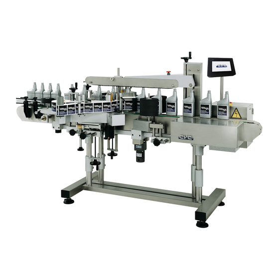
OPERATION MANUAL
FRONT/BACK LABELER
10861 Business Drive, Fontana, CA 92337
1.
Before operating the machine: Read thoroughly this Operating Manual to ensure the safety of the
personnel and to keep the machine in good conditions.
2.
Machine adjustment and parts changeover are only to be done by qualified and properly trained
engineers.
Model CVC 400
CVC TECHNOLOGIES, INC.
TEL: (909) 355-0311
FAX: (909) 355-0411
(ISO 9001:2000 Certified)
Advertisement
Table of Contents
Troubleshooting

Subscribe to Our Youtube Channel
Related Manuals for CVC CVC 400

Summary of Contents for CVC CVC 400
- Page 1 OPERATION MANUAL FRONT/BACK LABELER Model CVC 400 CVC TECHNOLOGIES, INC. 10861 Business Drive, Fontana, CA 92337 TEL: (909) 355-0311 FAX: (909) 355-0411 (ISO 9001:2000 Certified) Before operating the machine: Read thoroughly this Operating Manual to ensure the safety of the personnel and to keep the machine in good conditions.
-
Page 2: Table Of Contents
2011.3.10 CVC TECHNOLOGIES, INC. CVC 400 OPERATION MANUAL CONTENTS ABOUT THIS MANUAL About This Manual ....................1-1 Additional Information..................1-1 SPECIFICATIONS Machine Specifications..................2-1 Label Specifications .................... 2-2 Hot Stamp Printer Specifications (Optional)............2-5 SAFETY REGULATIONS General Safety Rules ................... 3-1 Warning Signs..................... - Page 3 CVC TECHNOLOGIES, INC. FRONT/BACK LABELER CVC 400 OPERATION MANUAL PREPARATION BEFORE OPERATION Inspection before Operation ................. 9-1 Installing the Label Roll..................9-3 Label Wipe-on Roller Mounting ................9-5 Hot Stamp Printer Preparation (Optional).............. 9-7 OPERATING PROCEDURE 10.1 Air Regulator Set Check (Optional) ............... 10-1 10.2...
- Page 4 CVC TECHNOLOGIES, INC. FRONT/BACK LABELER CVC 400 OPERATION MANUAL 15.3 Electrical Parts ....................15-3 TROUBLESHOOTING 16.1 Troubleshooting for Labeler.................. 16-1 16.2 Troubleshooting for C60 Hot Stamp Printer (Optional)........... 16-3 16.3 Error Message ....................16-4 APPENDIX 17.1 42A5BEPM-E3C4183 (Bodine) for Conveyor ............17-2 17.2...
- Page 5 OPERATION MANUAL Dear Customer, Thank you for purchasing a CVC 400 Labeling Machine. We at CVC hope you will find that the Model CVC 400 meets or exceeds your expectations and requirements for an affordable, reliable and innovative addition to your packaging operation.
- Page 6 FRONT/BACK LABELER CVC 400 OPERATION MANUAL PREFACE The CVC 400 front/back labeler is an advanced automatic labeling system. The system features high labeling speed and the most easy-to-operate control panel. The unique design of CVC 400 AUTO ADJ: ● Labeling speed is automatically synchronized with conveyor speed to ensure quality labeling.
-
Page 7: About This Manual
CVC TECHNOLOGIES, INC. CVC 400 OPERATION MANUAL ABOUT THIS MANUAL About This Manual This Operation Manual has been written by observing the CE directives, the main purpose of the regulation is in relation to the protection of personal safety and the maintenance of the machine in good conditions, as it is intended to provide the proper operation procedures to avoid causing danger and damages to persons and to the machine. -
Page 8: Specifications
CVC 400 OPERATION MANUAL SPECIFICATIONS Machine Specifications * Some features or different product formats will require additional attachments and changeover parts, please consult CVC for the purchase. Stepper Motor: 103H8222-5242 (Sanyo) - Conveyor Motor: Standard (3½”): 130 Vdc, 1/4HP (Bodine) Horse Power Special Type (6”): DC 130 Vdc, 1/3 HP (Bodine) - Page 9 CVC TECHNOLOGIES, INC. CVC 400 OPERATION MANUAL Machine Dimension L:2,435 W:1,280 x H: 1,480 (mm) 95 ¾" x 50 ½" x 58 ¼" a. Standard: WL4G, for general container Product Sensor b. Optional: WL9-2N, Special type for transparent container with dry powder...
-
Page 10: Label Specifications
CVC TECHNOLOGIES, INC. CVC 400 OPERATION MANUAL 2.2 Label Specifications 15~150mm (⅝" ~ 6") Label Width Label Length 15 ~250 mm (⅝"~ 10") Backing Paper Translucent backing paper Label Roll Inner Diameter. Standard: 76 mm (3") Optional: 38 mm (1½ ") Max. - Page 11 CVC TECHNOLOGIES, INC. CVC 400 OPERATION MANUAL 2.2.3 Label Rolled Outside (LRO) (Common Use) a. Label Roll for Labeling Head A: The labels are rolled outside in a clockwise direction. The space for hot stamp code should be reserved if such feature is used, and the hot stamp printer should be adjusted to meets this position.
- Page 12 CVC TECHNOLOGIES, INC. CVC 400 OPERATION MANUAL 2.2.4 Label Rolled Inside (LRI) (Uncommon) a. Label Roll for Labeling Head A: The labels are rolled inside in a counterclockwise direction. The space for hot stamp code should be reserved if necessary, and the hot stamp printer should be adjusted to meets this position.
-
Page 13: Hot Stamp Printer Specifications (Optional)
CVC TECHNOLOGIES, INC. CVC 400 OPERATION MANUAL Hot Stamp Printer Specifications (Option) Model: C60 Print Type Nickel alloy for standard sizes, brass for 1.3 mm type Print Sizes Standard size: 1.5mm, 2.0mm, 2.5mm Special size: 1.3mm Air Consumption ℓ /min (based on 300 strokes per minute) - Page 14 CVC TECHNOLOGIES, INC. CVC 400 OPERATION MANUAL 2.3.2 Type and Related Specifications Type Height Type Width Line Line Spacing Line Spacing Character Number Brass Type Number Narrow Type Chase Wide Type Chase (Max. Length) B1.3 1.5 mm 1.3 mm 2 mm 3 mm (15.6 mm)
- Page 15 CVC TECHNOLOGIES, INC. CVC 400 OPERATION MANUAL 2.3.3 Sample of Stamps Numbers 2.3.3.1 Brass Type for Wide Line-Spacing Fig 2.3-4 2.3.3.2 Brass Type for Narrow Line-Spacing Fig 2.3-5 2.3.3.3 Nickel Alloy Type Fig 2.3-6 2 - 8...
-
Page 16: Safety Regulations
CVC TECHNOLOGIES, INC. CVC 400 OPERATION MANUAL SAFETY REGULATIONS 3.1 General Safety Rules The safety regulations have been provided purely as a guide for the safety of all personnel involved in the operation, cleaning and maintenance of the equipment covered by this instruction manual. Please ensure that you have read and understood all safety notices before operating the equipment covered by this instruction manual, and that the recommendations here enclosed are strictly followed. -
Page 17: Warning Sign Placements
CVC TECHNOLOGIES, INC. CVC 400 OPERATION MANUAL 3.3 Warning Sign Placements Fig 3.3-1 3 - 2... -
Page 18: Important Safety Notices
CVC TECHNOLOGIES, INC. CVC 400 OPERATION MANUAL 3.4 Important Safety Notices Please observe following important safety notices. Directions should be given to operating personnel ensuring the safety regulations are observed. Heed all warning signs placed on the machine by the manufacturer. - Page 19 CVC TECHNOLOGIES, INC. CVC 400 OPERATION MANUAL Be sure that the operator knows the precise location of the emergency stop button, so that it can be pressed in time upon any emergency situation. Before machine start-up, also ensure that both the Stop Button and the Emergency stop button are in “0”...
- Page 20 CVC TECHNOLOGIES, INC. CVC 400 OPERATION MANUAL Only products listed in the order confirmation may be processed by the equipment covered by this instruction manual. Before processing any other kind of product please contact your nearest agent or sales distributor.
- Page 21 CVC TECHNOLOGIES, INC. CVC 400 OPERATION MANUAL Always switch OFF the main power switch before connecting or disconnecting an electrical connection. The equipment should be serviced by qualified personnel when the equipment does not appear to operate normally or exhibits a marked change in performance.
- Page 22 CVC TECHNOLOGIES, INC. CVC 400 OPERATION MANUAL When during cleaning or maintenance no power is required, always switch OFF and padlock the main power switch. The electronic equipment inside the electronics cabinet(s) may still be live even when the main power switch is switched OFF ! Always remove the power supply cord from the outlet prior to cleaning, inspection or maintenance work.
-
Page 23: Installation
CVC TECHNOLOGIES, INC. CVC 400 OPERATION MANUAL 4. INSTALLTION Standard Area Conditions a. Place the machine on a flat surface. Room temperature should range between 50°F ~ 104°F (10°C-40°C). It is recommended that the temperature of the area be at around 70 °F (25°C). Keep area free of vibration, and free of gaseous chemicals. -
Page 24: Transportation Precautions
CVC TECHNOLOGIES, INC. CVC 400 OPERATION MANUAL 4.3 Transportation Precautions Remove the top cover first, and then open the 4-side panels carefully. Keep the bottom wood base for later forklift transportation. b. Check the machine and its accessories for shipping damage. - Page 25 CVC TECHNOLOGIES, INC. CVC 400 OPERATION MANUAL Fig 4.4-1 Fig 4.4-2 4 - 3...
-
Page 26: Positioning And Adjustment Of Machine Level And Height
CVC TECHNOLOGIES, INC. CVC 400 OPERATION MANUAL Positioning and Adjustment of Machine Level and Height a. Align the conveyor center line with the predetermined center line drawn on the floor. Ensure that machine outer boundaries fit in the previously drawn contour line. -
Page 27: Installation Procedures
CVC TECHNOLOGIES, INC. FRONT/BACK LABELER CVC 400 OPERATION MANUAL INSTALLATION PROCEDURES Power Connection Connection of the electricity supply to the machine is necessary for the operation of its electrical components. Only use 3-hole socket and properly grounded. a. Connect the main power cord of the machine to the safety NFB breakers on the power source, ensuring that the voltage and amperage meet machine’s requirements. -
Page 28: U-Type Spring Clip Mounting (Optional)
CVC TECHNOLOGIES, INC. FRONT/BACK LABELER CVC 400 OPERATION MANUAL U-Type Spring Clip Mounting (Optional) Follow the illustrations given below to mount the U type spring clip before using 38mm label web. It is designed to fasten the label roll when 38mm label web is applied. -
Page 29: C60 Printing Type Arrangement (Optional)
CVC TECHNOLOGIES, INC. FRONT/BACK LABELER CVC 400 OPERATION MANUAL C60 Printing Type Arrangement (Optional) a. Whenever possible, it is suggested that the letter type are arranged in a centered and balanced way within the type holder area for better results. (Depend on the actual situation of the label imprinting.) Fig 5.4-1... -
Page 30: Machine General Layout
CVC TECHNOLOGIES, INC. CVC 400 OPERATION MANUAL MACHINE GENERAL LAYOUT Parts Identification 6.1.1 Front/Back Labeler with Separator (Wheel / Screw) ○ ○ Separator - Screw Separator - Wheel Fig 6.1-1 6 - 1... - Page 31 CVC TECHNOLOGIES, INC. CVC 400 OPERATION MANUAL 6.1.2 Front/Back Labeler with Alignment Assembly (Belt/Chain) ○ Alignment chain assy. Alignment belt assy. ○ Fig 6.1-2 6 - 2...
- Page 32 CVC TECHNOLOGIES, INC. CVC 400 OPERATION MANUAL Nomenclature Nomenclature Height adj. knob for top hold-down bar Top Hold-down bar Assembly Emergency Stop Button Separating screw device (optional) Labeling Roller Swiveling caster Tension arm Rewind spool disk HHT control panel Control box...
- Page 33 CVC TECHNOLOGIES, INC. CVC 400 OPERATION MANUAL Hot Stamp Printer (Optional) Stamp height adj. knob Foil roller Air cylinder Control fit of type chase Type chase Hot stamp silicon pad Foil tape Ribbon brake Temperature indicator (Red=too low, Green=ready) Temperature controller...
-
Page 34: Machine Parts Functions
CVC TECHNOLOGIES, INC. CVC 400 OPERATION MANUAL Machine Parts Functions A brief description of the main components functions of the machine are given in this section, please refer to “Machine Parts Identification” section for the identification of the parts on the machine. -
Page 35: Machine Control Parts Functions
CVC TECHNOLOGIES, INC. CVC 400 OPERATION MANUAL Machine Control Parts Functions Refer to section 6.1 for the location of the different control parts. 6.3.1 Main Power Switch This main power switch is used to connect or disconnect the machine from the power source, putting the switch in position “O”... -
Page 36: Pneumatic Control System (Optional)
CVC TECHNOLOGIES, INC. CVC 400 OPERATION MANUAL Pneumatic Control System (Optional) Pneumatic control system is provided to control the C60 hot stamp printer if equips with this printer. 6.4.1 Air Regulating Set Responsible of regulating the compressed air connected to the machine into desired pressure. The air flowing is controlled by the air flow adj. -
Page 37: General Layout And Dimensions
CVC TECHNOLOGIES, INC. CVC 400 OPERATION MANUAL General Layout and Dimensions Fig 6.5-1 6 - 8... -
Page 38: Power Box
CVC TECHNOLOGIES, INC. CVC 400 OPERATION MANUAL POWER BOX Refer to the Chapter related to “Electrical Diagrams” for more detailed information regarding the functions of the electrical components. 7 - 1... -
Page 39: Locations Of Printed Circuit Board (A)
DC Motor Driver for Product Separator installed, C12-PP is used instead of C8-R. Wheel C12-PP DC Motor Driver for Push & Press Attachment (optional) * Push & Press function is available only the system is equipped by CVC. 7 - 2... - Page 40 CVC TECHNOLOGIES, INC. CVC 400 OPERATION MANUAL Locations of Printed Circuit Board (B) C4: Master Board C15: Interface Board C16: Transformer C17: DC Power Supply C18: Power Board 7 - 3...
-
Page 41: Printed Circuit Board
Indicator List Item Lamp Function Power ON On "Labeling" Labeling Head "B" (CVC 400 and CVC 430) Spare – for future use Spare – for future use Spare – for future use Labeling Head "A" (CVC 400 and CVC 430) Spare –... - Page 42 CVC TECHNOLOGIES, INC. CVC 400 OPERATION MANUAL 7.2.2 C15: Interface Board Fusing and Indicators Item Fuse Function Working Trouble Indicator Fuse Size STEP B (D38) Fuse for Labeling Head "B" 4A (20mm) STEP A (D37) Fuse for Labeling Head "A"...
- Page 43 CVC TECHNOLOGIES, INC. CVC 400 OPERATION MANUAL 7.2.3 C7, C7-1: Stepper Motor Driver for Labeling Head Dip Switch setting: Left: Overheating protection Spare – for future use. a. Left: Head A stepper motor revolution switch (right hand labeling head, standard) b.
- Page 44 CVC TECHNOLOGIES, INC. CVC 400 OPERATION MANUAL 7.2.4 C8-R, C10, C11: DC Motor Driver for Label Roller, Product Separator Wheel, Conveyor C12-PP: DC Motor Driver for Press & Push Attachment (Optional) 5V VIN STOP U7 Power supply GND (ORG) indicator ○...
- Page 45 CVC TECHNOLOGIES, INC. CVC 400 OPERATION MANUAL Note: All the LED indicators should be ON when power is ON (D11 red LED is flashing or ON). The standard operation procedures of MV are as below: a. Speed adjustment: Conveyor speed: Press product speed twice, set the value at 255 (max) and then press ENTER key.
- Page 46 CVC TECHNOLOGIES, INC. CVC 400 OPERATION MANUAL 7.2.5 C17: DC Power Supply If LED D41on interface board is not lit when power is on, it indicates no output for switch power 5V. If LED D42 is not lit when power is on, it indicates no output for switch power 12V, replace a new one if necessary.
- Page 47 CVC TECHNOLOGIES, INC. CVC 400 OPERATION MANUAL 7.2.6 C18: Power Board a. F2 fuse is burned if transformer is short circuit. b. Check LED 36, D37 and D38 on the interface board. If the three LEDs are lit, it indicates both the power board and fuse are not functional.
-
Page 48: Hht Display Instructions
CVC TECHNOLOGIES, INC. CVC 400 OPERATION MANUAL HHT DISPLAY INSTRUCTION Control Panel Descriptions Fig 8.1-1 Symbol Description green Start conveyor Stop conveyor Function selecting keys Value modification keys: (-) decreases and (+) increases (e.g. (-) for slower and (+) for faster) To select different displays. - Page 49 CVC TECHNOLOGIES, INC. CVC 400 OPERATION MANUAL Labeling Head A (Fig 8.1-2): Toggles labeling head A ON or OFF, a symbol on the display up-right corner shows the current labeling heads, the right rectangle in the symbol becomes black to indicate that the labeling head A is active.
- Page 50 CVC TECHNOLOGIES, INC. CVC 400 OPERATION MANUAL Label head A Label head B Fig 8.1-2 Note: * When only a single labeling head is applied (e.g. one side labeling for round/square/flat bottle), the one not used should be switched off.
-
Page 51: Lcd Display Descriptions
CVC TECHNOLOGIES, INC. CVC 400 OPERATION MANUAL LCD Display Descriptions LCD-1 F1 AUTO ADJ F2 CALL MEMORY F3 CURRENT MEM F1: Select this key for new products: new bottle (container) or new labels. F2: Call job setting from memory for further reuse (Job No. 1 ~ 50). - Page 52 CVC TECHNOLOGIES, INC. CVC 400 OPERATION MANUAL LCD-5 F1 PD LEN F2 LA LEN F3 LB LEN F1: Product diameter measured by the computer. F2: Head A: Label length measured by the computer. F3: Head B: Label length measured by the computer.
-
Page 53: Auto Adj Display Sequence
CVC TECHNOLOGIES, INC. CVC 400 OPERATION MANUAL AUTO ADJ Display Sequence CVC 400 * Optional function 8 - 6... -
Page 54: Preparation Before Operation
CVC TECHNOLOGIES, INC. CVC 400 OPERATION MANUAL 9. PREPARATION BEFORE OPERATION Inspection before Operation Ensure that no foreign objects or tools are left in the machine. Ensure that air and power supply are normal. Check that there are no loose or damaged parts in the machine. - Page 55 CVC TECHNOLOGIES, INC. CVC 400 OPERATION MANUAL b. Label rolled inside (Copy Positions 5.6.7.8 of Label Position Chart, Fig 9.3.5). Fig.9.2.1-2 9.2.2 Rewind Spool Tension Adjustment Use a metal clip to fasten the label web backing paper onto the rewind spool, and then manually rotate the rewind spool one rotation to ensure a proper attachment.
- Page 56 CVC TECHNOLOGIES, INC. CVC 400 OPERATION MANUAL 9.2.3 Label Advance Roller Lock and Rewind Roller Lock After installing the label roll, both label advance roller lock and rewind roller lock should be firmly locked. An improper locking will lead to an abnormal label length (○...
- Page 57 CVC TECHNOLOGIES, INC. CVC 400 OPERATION MANUAL 9.2.5 Label Position Chart a. Copy Position 1, 2, 3 and 4 are used to designate labels rolled so they are positioned on the outside of the web. b. Copy Position 5, 6, 7 and 8 are used to designate labels rolled so they are positioned on the inside of the web.
-
Page 58: Label Wipe-On Roller Mounting
CVC TECHNOLOGIES, INC. CVC 400 OPERATION MANUAL Label Wipe-on Roller Mounting (Option) For proper front/back labeling, the wipe-on roller on each side should be mounted as shown in Fig 9.3-2. The distance from the peel blade should be carried out proper adjustment before labeling. -
Page 59: Hot Stamp Printer Preparation (Optional)
CVC TECHNOLOGIES, INC. CVC 400 OPERATION MANUAL Hot Stamp Printer Preparation (Optional) This is an optional coding and dating printer. The printing and labeling are accomplished synchronously; the printer must be properly adjusted and ready to operate before starting labeling. -
Page 60: Air Regulator Set Check (Optional)
CVC TECHNOLOGIES, INC. CVC 400 OPERATION MANUAL 10. OPERATION INSTRUCTION a. Ensure that electric supply and compressed air are properly connected. b. Ensure that the HHT Control panel plug is properly connected to the HHT socket on the machine. c. It is necessary to adjust the machine working parts to a proper position according to the product to be labeled and the label to be applied. -
Page 61: Operating Procedure
CVC TECHNOLOGIES, INC. CVC 400 OPERATION MANUAL 10.2 Operating Procedure a.. Turn on the main power switch on the top of the power box (Fig 6.1-2). b. First machine identification screen is displayed as below: CVC 400 VER X.X After 3 seconds, the display is changed to:... - Page 62 CVC TECHNOLOGIES, INC. CVC 400 OPERATION MANUAL 3) Label sensitivity is set after the above two readout displays. After that, the display is changed to: PLACE PRODUCT ON CONVEYOR FOR TEST 4) Place one product on the conveyor to the left of the product sensor when conveyor starts moving slowly.
- Page 63 CVC TECHNOLOGIES, INC. CVC 400 OPERATION MANUAL Press to enter bottle diameter and then press key to confirm. Press to enter label length for the labeling head A, and then press key to confirm. Press to enter label length for the labeling head B, and then press key to confirm.
-
Page 64: Machine Set-Up And Adjustment
CVC TECHNOLOGIES, INC. CVC 400 OPERATION MANUAL 11. MACHINE SET-UP AND ADJUSTMENT For personnel safety and avoiding machine damage, always SWITCH OFF the power before any machine adjustment. All machine adjustments should be accomplished by qualified technicians. Most adjustable parts of the machine are provided with guide rulers or numerical hand wheels, proper adjustments are determined through factory test and should not be changed unless necessary. -
Page 65: Product Alignment Mechanism Adjustments
CVC TECHNOLOGIES, INC. CVC 400 OPERATION MANUAL 11.2 Product Alignment Mechanism Adjustments After products pass the separator wheels, the alignment belt may line up the products in alignment for correct labeling (Fig 11.2-1). The alignment mechanism adjustment procedures are illustrated as follows. -
Page 66: Label Peel Blades Adjustments (Head A And Head B)
CVC TECHNOLOGIES, INC. CVC 400 OPERATION MANUAL 11. 4 Label Peel Blades Adjustments (Head A and Head B) Adjust the spacing between the two label-peel blades and the product for proper labeling. a. Place a product on the conveyor between the two label peel blades. -
Page 67: Output Adjustments
CVC TECHNOLOGIES, INC. CVC 400 OPERATION MANUAL 11.6 Labeling Rollers Adjustments (Square/Flat Bottles) a. Place a product between the two labeling rollers, and then adjust the width using the lower adjustment knob (Fig 6.1-2). b. Adjust the rollers to a proper height to meet the label position, using the height adjustment handwheel (Fig 6.1-2). -
Page 68: Label Remaining Quantity Adjustments
CVC TECHNOLOGIES, INC. CVC 400 OPERATION MANUAL 11.8 Label Remaining Quantity Adjustments Used for label quantity control. Enter the number of the labels, the display shows the current remaining number of the labels, and it may alert the operator with an alarm when the remaining number of the labels falls below "500"... - Page 69 CVC TECHNOLOGIES, INC. CVC 400 OPERATION MANUAL Fig 11.10-1 Fig 11.10-2 c. The following figure shows correct labeling performance, the backing paper should stretch flat and close to the peel blade, and the label should be slightly tensed by the advancing bottle.
-
Page 70: Label Extension (Extnsn) Adjustments
CVC TECHNOLOGIES, INC. CVC 400 OPERATION MANUAL 11.11 Label Extension (EXTNSN) Adjustments a. F2 EXTNSN refers to the length of label portion that extends beyond the tip of the peel blade. See the following illustration. Fig 11.11-1 b. Normally F2 EXTNSN ranges between 1 and 5mm. In some special cases the distance may be longer than 5mm. -
Page 71: Labeling Position (Positn) Adjustments
CVC TECHNOLOGIES, INC. CVC 400 OPERATION MANUAL 11.12 Labeling Position (POSITN) Adjustments a. This labeling position refers to the horizontal position where the label is applied. Fig 1 Fig 2 Fig 3 Fig 4 Bottle Label Fig 11.12-1 b. Correct labeling position shown on the Fig. -
Page 72: Labeling Sensing (Lab Sens) Adjustments
CVC TECHNOLOGIES, INC. CVC 400 OPERATION MANUAL 11.13 Labeling Sensing (LAB SENS) Adjustments a. Label sensing refers to the sensing of the backing paper translucency or opacity; the sensitivity of the label sensor can be adjusted. The product (bottle), label thickness, material and opacity will be considered together, as the sensor sensitivity is automatically adjusted by the SelfSet and no manual adjustment is necessary. - Page 73 CVC TECHNOLOGIES, INC. CVC 400 OPERATION MANUAL (Х) (Х) Fig 11.13-1 g. Thinner or clear portions of the label may be mistaken as gaps, causing incomplete label dispensing (half label is dispensed), the label will be abnormally pulled out by the bottle instead of smooth dispensing.
-
Page 74: Product Sensor Adjustments
CVC TECHNOLOGIES, INC. CVC 400 OPERATION MANUAL 11.14 Product Sensor Adjustments The function of product sensor (WL-4G) is to detect bottle width (a tolerance of 1~2mm showed on the LCD display is acceptable), and then sends the signal of bottle width to SelfSet to perform labeling job. -
Page 75: Product Separator Wheel Adjustments
CVC TECHNOLOGIES, INC. CVC 400 OPERATION MANUAL 11.15 Product Separator Wheel Adjustments a. Press once to turn on the product separator wheel. b. Press twice to turn off the product separator. c. Press three times to change the speed of the separator wheel. The display will show the... -
Page 76: Clear Label Sensor Adjustment Procedures
CVC TECHNOLOGIES, INC. CVC 400 OPERATION MANUAL 11.17 Clear Label Sensor Adjustment Procedures (Option) Note: Please refer to Appendix “User’s Guide for LRD6110 Label Sensor” for more detail information. a. Thread the labels around the rollers and thru the label sensor as described by the manual. -
Page 77: Complementary Tools
CVC TECHNOLOGIES, INC. CVC 400 OPERATION MANUAL COMPLEMENTARY TOOLS 12.1 Complementary Tools Note: Tool set may differ when machine is sold as part of on integrated line. 12.1.1 Tool Bo A tool box is provided with the shipment, containing some useful tools (Fig 12.1-1). - Page 78 CVC TECHNOLOGIES, INC. CVC 400 OPERATION MANUAL 12.1.3 U-Type Spring Clip (Option) Designed for fastening a 38 mm Labeling web (Fig 12.1-3). Fig 12.1-3 12 - 2...
-
Page 79: Maintenance
CVC TECHNOLOGIES, INC. CVC 400 OPERATION MANUAL 13. MAINTENANCE 13.1 General Precautions a. Safety ․Before performing any maintenance job or cleanup, ensure that the power is disconnected. ․Always take the necessary safety measures to protect both machine and personnel when carrying out maintenance job b. -
Page 80: Air Regulator Set Maintenance (Optional For C60 Hot Stamp Printer)
CVC TECHNOLOGIES, INC. CVC 400 OPERATION MANUAL 13.3 Air Regulator Set Maintenance (Optional for C60 Hot Stamp Printer) The air regulator is equipped with an air filter; drain the accumulated water of the reservoir and check after every usage. Inspect and ensure the lubrication oil reservoir is sufficient. - Page 81 CVC TECHNOLOGIES, INC. CVC 400 OPERATION MANUAL 14. ELECTRICAL AND PNEUMATIC DIAGRAMS 14 - 1...
-
Page 82: Electric Pin Descriptions
CVC TECHNOLOGIES, INC. CVC 400 OPERATION MANUAL 14.1 ELECTRIC Pin Description 14.1.1 Side-Plate (Power Box) Labeling Head B (Left, X1), Labeling Head A (Right, X2) ※ Stepper Motor Coil Labeling Head B (Left, X1) Labeling Head A (Right, X2) Pin No. Color Definition Pin No. - Page 83 CVC TECHNOLOGIES, INC. CVC 400 OPERATION MANUAL Digital I/O Pin No. Color Definition Pin No. Color Definition Pin No. Color Definition DC 12 V Conveyor encoder Encoder, BLK Product sensor PH B Backlog sensor DC 12 V Wrapping encoder Clear label sensor, PH A BLK P&P sensor...
- Page 84 CVC TECHNOLOGIES, INC. CVC 400 OPERATION MANUAL 14.1.2 Wiring Duct ※ The input components should be matched with DC 12VG, and the output components should be matched with DC 24V or DC 12V (depending on the voltage of the component applied, motor is excluded) Stepper Motor Coil Labeling Head B (Left, X1) <4P>...
- Page 85 CVC TECHNOLOGIES, INC. CVC 400 OPERATION MANUAL Digital Sensor Product Sensor <3P> P&P Sensor <3P> Pin No. Color Jump No. Definition Pin No. Color Jump No. Definition J31-2 DC 12V J31-2 DC 12V J31-3 DC 12VG J31-3 DC 12VG J31-11 Signal cable J31-12 Signal cable Backlog &...
- Page 86 CVC TECHNOLOGIES, INC. CVC 400 OPERATION MANUAL Label Sensor Head B (Left, X1) <7P> Head A (Right, X2) <7P> Pin No. Color Jump No. Definition Pin No. Color Jump No. Definition DLAV1, Sending signal input DLAV2, Sending signal input J32-4...
-
Page 87: Pneumatic Diagrams
CVC TECHNOLOGIES, INC. CVC 400 OPERATION MANUAL 14.2 Pneumatic Diagrams 14 - 7... -
Page 88: Electrical Diagrams
CVC TECHNOLOGIES, INC. CVC 400 OPERATION MANUAL 14.3 Electrical Diagrams 14.3.1 Labeler 14 - 8... - Page 89 CVC TECHNOLOGIES, INC. CVC 400 OPERATION MANUAL 14.3.2 C60 Hot Stamp Printer (Optional) 14 - 9...
- Page 90 CVC_F26_001 CVC TECHNOLOGIES, INC. No.361, Renhua Rd. Dali City, Taichung County, Taiwan Phone. 886-4-24969922 Company / customer Job number E06001C Project description Manufacturer (company) CVC TECHNOLOGIES, INC. Path Project name E06001 make Type Place of installation +MP1 Power supply 1Φ110 V AC...
- Page 91 S1000997 =E060+MP1/01.4:D Electric Valve SY5120-5G-01 S8000091 =E060+MP1-01Y1 Solenoid valve =E060+MP1/01.3:D =E060+MP1-PLT-168P Connector Connector PLT-168P S1000227 =E060+MP1/01.2:B E06001C Date 2010/10/4 REPORT Drawn 20020401 PARTSLIST Parts list : S1000537 - S1000227 Designed Page E06001C CVC TECHNOLOGIES,INC Modification Date Name Next =E060+BM/01 Approved...
- Page 92 -01E1 -01B1 -01S1 -01F1 -01S3 -01Y1 -01S2 -01U1 -PLT-168P E06001C Date 2010/10/7 E060 Drawn 20020401 Parts Figure Designed Designed Page E06001C CVC TECHNOLOGIES,INC Modification Date Name Next +MP1/01 Approved...
- Page 93 -01W1 -01U1 -01S2 -01S3 -01X1 -01F1 -01S1 -01Y1 -01V1 -01E1 -01B1 Electric Valve Ribbon Sensor Temperature Heater Thermocouple (Option) Controller E06001C Date 2010/10/7 E060 Drawn 20020401 Power circuitry Designed Designed Page E06001C CVC TECHNOLOGIES,INC Modification Date Name Approved Next Approved...
- Page 94 CVC_F26_001 CVC TECHNOLOGIES, INC. No.361, Renhua Rd. Dali City, Taichung County, Taiwan Phone. 886-4-24969922 Company / customer Job number E06002C Project description Manufacturer (company) CVC TECHNOLOGIES, INC. Path Project name E06002 make Type Place of installation +MP1 Power supply 1Φ110 V AC...
- Page 95 Solenoid valve =E060+MP1/01.3:D =E060+MP1-01Y2 Solenoid valve 525158 MHP3-M1H-3/2O-1/8 FESTO S8000681 =E060+MP1/01.3:D Connector PLT-168P S1000227 =E060+MP1-PLT-168P Connector =E060+MP1/01.2:B E06002C Date 2010/10/4 REPORT Drawn 20020401 PARTSLIST Parts list : S1000537 - S1000227 Designed Page E06002C CVC TECHNOLOGIES,INC Modification Date Name Next =E060+BM/01 Approved...
- Page 96 -01E1 -01B1 -01S1 -01F1 -01Y1 -01S3 -01S2 -01Y1 -01U1 -PLT-168P E06002C Date 2010/10/7 E060 Drawn 20020401 Parts Figure Designed Designed Page E06002C CVC TECHNOLOGIES,INC Modification Date Name Next +MP1/01 Approved...
- Page 97 -01U1 -01S2 -01S3 -01X1 -01F1 -01Y2 -01V1 -01Y1 -01S1 -01E1 -01B1 Electric Valve Ribbon Sensor Temperature Heater Thermocouple (Option) Controller E06002C Date 2010/10/4 E060 Drawn 20020401 Power circuitry Designed Designed Page E06002C CVC TECHNOLOGIES,INC Modification Date Name Approved Next Approved...
-
Page 98: Parts List
Push & Press Sponge, (C Type), (Optional) W1230435 E3XNA11+E32CC200 C7 (DRV5) Stepper motor drive for labeling head C10 (DCMD) Motor drive for conveyor * (A), (C), (E) above indicate model CVC 400A, CVC 400C, CVC 400E respectively. 15 - 1... - Page 99 Hot stamp silicone pad S1000537 KBSGN-43H05 Thermal couple S8000091 SY5120, SMC Solenoid valve S1000491 110V – 60W **Heater S8000627 547570 Swivel module (Air cylinder) *This part must be procured only from CVC to avoid any damage to the printer. 15 - 2...
- Page 100 CVC TECHNOLOGIES, INC. CVC 400 OPERATION MANUAL 15.3 Electrical Part List Reference Item Part Number Description Specification Remark Number TO-2-1 S1000921 Main Power Switch S1000792 Master Board S1000791 Interface Board PWR5 S1000925 Power Board DCMD-8 S1000789 DC Motor Drive DC Motor Drive,...
-
Page 101: Troubleshooting
CVC TECHNOLOGIES, INC. CVC 400 OPERATION MANUAL 16. TROUBLESHOOTING 16.1 Troubleshooting for Labeler Problem Possible Cause Suggested Solution Incomplete label dispensing causes a. Improper label sensor adjustment Remove the label in the label sensor backing paper to be pulled by the slot;... - Page 102 CVC TECHNOLOGIES, INC. CVC 400 OPERATION MANUAL Two labels dispensed at a time The sensitivity values of the labels a. Increase label sensitivity value. and the backing papers are too close. This will cause no signal is sent to stop it.
-
Page 103: Troubleshooting For C60 Hot Stamp Printer (Optional)
CVC TECHNOLOGIES, INC. CVC 400 OPERATION MANUAL 16.2 Troubleshooting for C60 Hot Stamp Printer Problem Possible Cause Suggested Solution 1. Heating indicator keeps ON Heater malfunction Replace with a new heater. (orange), fail to OFF (green). 2. Thermal indicator keeps on (red) or... -
Page 104: Error Message
CVC TECHNOLOGIES, INC. CVC 400 OPERATION MANUAL 16.3 Error Message a. Product sensor error: Problem: Product sensor malfunctions or PRODUCT SENSOR ERR PLEASE CHECK product is abnormal. After solving the problem, press START PRESS ‘START’ KEY key for 5 seconds to restart the machine. -
Page 105: Appendix
CVC TECHNOLOGIES, INC. CVC 400 OPERATION MANUAL 17. APPENDIX 17 - 1... -
Page 106: 42A5Bepm-E3C4183 (Bodine) For Conveyor
CVC TECHNOLOGIES, INC. CVC 400 OPERATION MANUAL 17.1 42A5BEPM-E3C4183 (Bodine) for Conveyor 17 - 2... -
Page 107: Clear Label Sensor (Lrd 6110) (Optional)
CVC TECHNOLOGIES, INC. CVC 400 OPERATION MANUAL 17.2 Clear Label Sensor (LRD 6110) (Option) 17 - 3... - Page 108 CVC TECHNOLOGIES, INC. CVC 400 OPERATION MANUAL 17 - 4...
- Page 109 CVC TECHNOLOGIES, INC. CVC 400 OPERATION MANUAL 17 - 5...
- Page 110 CVC TECHNOLOGIES, INC. CVC 400 OPERATION MANUAL 17 - 6...
- Page 111 CVC TECHNOLOGIES, INC. CVC 400 OPERATION MANUAL 17 - 7...
-
Page 112: Product Sensor (Wl 4G-2)
CVC TECHNOLOGIES, INC. CVC 400 OPERATION MANUAL 17.3 Product Sensor (WL 4G-2) 17 - 8...
Need help?
Do you have a question about the CVC 400 and is the answer not in the manual?
Questions and answers